How can I test DRAMs?
Sometimes you have to try your hand at repairing an old computer or console that uses these types of RAM and fortunately there are ways that help us find the bank (or more) faulty.
But why DRAMs? These dynamic RAMs (hence the name) unlike the static ones need to refresh their stored data by rewriting them often every few milliseconds. The data on these RAMs is stored and maintained by a charge of a capacitor present on the memory cell, but this capacitor even if it does not hold the charge for a long time and if the data is read the charge runs out much more quickly, so the data they must be rewritten both if it is read (only the line read) and periodically (all data present).
These RAMs were chosen for a simple reason, the cost! In fact, compared to SRAMs this model requires much less transistors in construction so you can have RAM with much more capacity at the cost of a SRAM 4 times smaller.
Well, now let's see how to solve the problems of these memories, often due to the deterioration of the capacitors they no longer keep the written data and a method to find the faulty RAM can be to place another one on top of it (Piggyback method), in this way the data will be written and stored on the two rams and if any data is lost on the faulty ram, it will be recovered by the good one.
Attention that it is not a foolproof system, in fact if the RAM has shorted pins, the one placed above will not be able to pass any data on the shorted line, moreover if there are more defective banks the computer may not start (if it does not have a system to check RAM at startup) and you won't know which other one is ruined.
This method instead requires you to build a small Arduino-based tester, the diagram is on the network and is very simple, the operation does nothing but write and read several times to verify that the data is actually correct.
You can find the information and the scheme at this link: https://forum.defence-force.org/viewtopic.php?t=1699
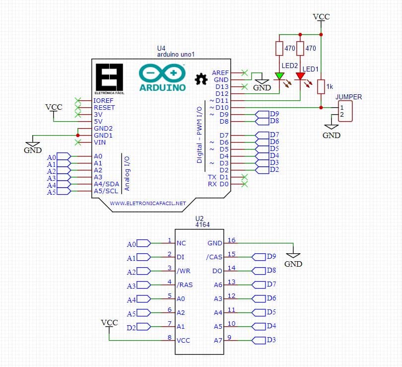
Since the scheme is drawn by hand, I put one redone following the original (by ISS):
Tester for 4164
# includes
#define DI 15 // PC1
#define DO 8 // PB0
#define CAS 9 // PB1
#define RAS 17 // PC3
#define WE 16 // PC2
#define XA0 18 // PC4
#define XA1 2 // PD2
#define XA2 19 // PC5
#define XA3 6 // PD6
#define XA4 5 // PD5
#define XA5 4 // PD4
#define XA6 7 // PD7
#define XA7 3 // PD3
#define XA8 14 // PC0
#define M_TYPE 10 // PB2
#define R_LED 11 // PB3
#define G_LED 12 // PB4
#define RXD 0 // PD0
#define TXD 1 // PD1
#define BUS_SIZE 9 // set to 7 if used for 4116
volatile int bus_size;
// SoftwareSerial USB (RXD, TXD);
const unsigned int a_bus [BUS_SIZE] = {
XA0, XA1, XA2, XA3, XA4, XA5, XA6, XA7, XA8
};
void setBus (unsigned int a) {
int i;
// correct function
for (i = 0; i <bus_size; i ++) {
if (bitRead (a, i) == 1) {
digitalWrite (a_bus [i], HIGH);
} else {
digitalWrite (a_bus [i], LOW);
}
}
}
void writeAddress (unsigned int r, unsigned int c, int v) {
/ * row * /
setBus (r);
digitalWrite (RAS, LOW);
/ * rw * /
digitalWrite (WE, LOW);
/ * val * /
digitalWrite (DI, (v & 1)? HIGH: LOW);
/* with the */
setBus (c);
digitalWrite (CAS, LOW);
digitalWrite (WE, HIGH);
digitalWrite (CAS, HIGH);
digitalWrite (RAS, HIGH);
}
int readAddress (unsigned int r, unsigned int c) {
int ret = 0;
/ * row * /
setBus (r);
digitalWrite (RAS, LOW);
/* with the */
setBus (c);
digitalWrite (CAS, LOW);
/ * get current value * /
ret = digitalRead (DO);
digitalWrite (CAS, HIGH);
digitalWrite (RAS, HIGH);
return ret;
}
void error (int r, int c)
{
unsigned long a = ((unsigned long) c << bus_size) + r;
digitalWrite (R_LED, LOW);
digitalWrite (G_LED, HIGH);
interrupts ();
Serial.print ("FAILED $");
Serial.println (a, HEX);
Serial.flush ();
while (1)
;
}
void ok (void)
{
digitalWrite (R_LED, HIGH);
digitalWrite (G_LED, LOW);
interrupts ();
Serial.println ("OK!");
Serial.flush ();
while (1)
;
}
void blink (void)
{
digitalWrite (G_LED, LOW);
digitalWrite (R_LED, LOW);
delay (1000);
digitalWrite (R_LED, HIGH);
digitalWrite (G_LED, HIGH);
}
void green (int v) {
digitalWrite (G_LED, v);
}
void fill (int v) {
int r, c, g = 0;
v % = 1;
for (c = 0; c <(1 < <bus_size); c++) {
green (g? HIGH: LOW);
for (r = 0; r <(1 < <bus_size); r++) {
writeAddress (r, c, v);
if (v! = readAddress (r, c))
error (r, c);
}
g ^ = 1;
}
blink ();
}
void fillx (int v) {
int r, c, g = 0;
v % = 1;
for (c = 0; c <(1 < <bus_size); c++) {
green (g? HIGH: LOW);
for (r = 0; r <(1 < <bus_size); r++) {
writeAddress (r, c, v);
if (v! = readAddress (r, c))
error (r, c);
v ^ = 1;
}
g ^ = 1;
}
blink ();
}
void setup () {
int i;
Serial.begin (9600);
while (! Serial)
; / * wait * /
Serial.println ();
Serial.print ("DRAM TESTER");
for (i = 0; i <BUS_SIZE; i ++)
pinMode (a_bus [i], OUTPUT);
pinMode (CAS, OUTPUT);
pinMode (RAS, OUTPUT);
pinMode (WE, OUTPUT);
pinMode (DI, OUTPUT);
pinMode (R_LED, OUTPUT);
pinMode (G_LED, OUTPUT);
pinMode (M_TYPE, INPUT);
pinMode (DO, INPUT);
digitalWrite (WE, HIGH);
digitalWrite (RAS, HIGH);
digitalWrite (CAS, HIGH);
digitalWrite (R_LED, HIGH);
digitalWrite (G_LED, HIGH);
// if using memory 4146 don't insert this loop if (digitalRead)… else ..
if (digitalRead (M_TYPE)) {
/ * jumper not set - 41256 * /
bus_size = BUS_SIZE;
Serial.print ("256Kx1");
} else {
/ * jumper set - 4164 * /
bus_size = BUS_SIZE - 1;
Serial.print ("64Kx1");
}
Serial.flush ();
digitalWrite (R_LED, LOW);
digitalWrite (G_LED, LOW);
noInterrupts ();
for (i = 0; i <(1 << BUS_SIZE); i ++) {
digitalWrite (RAS, LOW);
digitalWrite (RAS, HIGH);
}
digitalWrite (R_LED, HIGH);
digitalWrite (G_LED, HIGH);
}
void loop () {
interrupts (); Serial.print (“.”); Serial.flush (); noInterrupts (); fillx (0);
interrupts (); Serial.print (“.”); Serial.flush (); noInterrupts (); fillx (1);
interrupts (); Serial.print (“.”); Serial.flush (); noInterrupts (); fill (0);
interrupts (); Serial.print (“.”); Serial.flush (); noInterrupts (); fill (1);
ok ();
}
Build this circuit, program Arduino by downloading the .ino file or pasting the source code on an empty project of the Arduino ide and program it. With Arduino connected to a PC you can see the test status via the serial monitor, or visible via the LEDs.
Operation
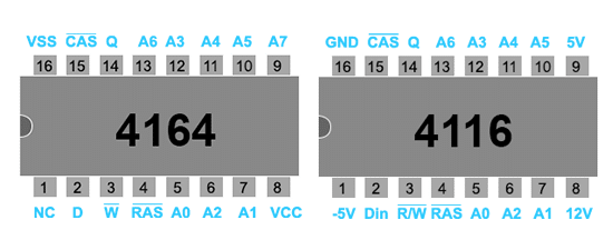
1. Select the type of RAM (4164 - 41256) using the jumper, if inserted it tests the 4164, if left open it tests the 41256.
2. Insert the RAM to be tested paying attention to the correct orientation (a polarity inversion will burn the RAM bank).
3. Power up the Arduino which will immediately start the test, wait a little more than a minute and if everything is ok the green LED will light up, otherwise the red one.
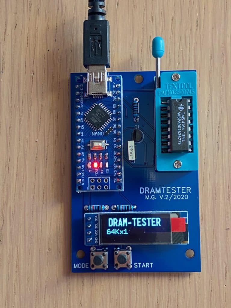
Another example of a DRAM tester (4164) V1
This is an embodiment of a tester similar to the one described above.
It is the first version I made and it only reads 4164-256.
The operation is slightly different and works with a display and two buttons, one to choose the type of RAM to be tested and one to start the test.
The various tests carried out are visible on the display as the final result.
In this case the power supply of the memory is managed by Arduino which will supply the RAM as soon as the test is started and will stop it when finished. A little safety to avoid burning the RAM if it is placed upside down.
Now it's up to you to invent your own tester or simply use the one described.
THE PREVIOUS CODE IS NOT GOOD FOR THIS TESTER.
And now here is the new tester also suitable for the 4116 V2
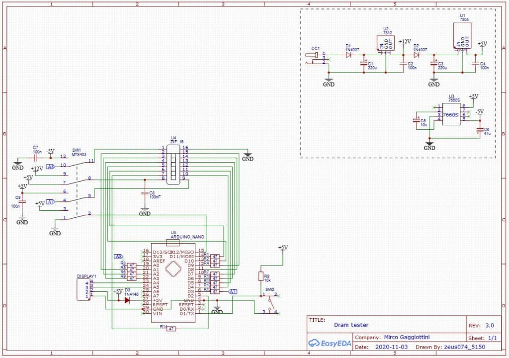
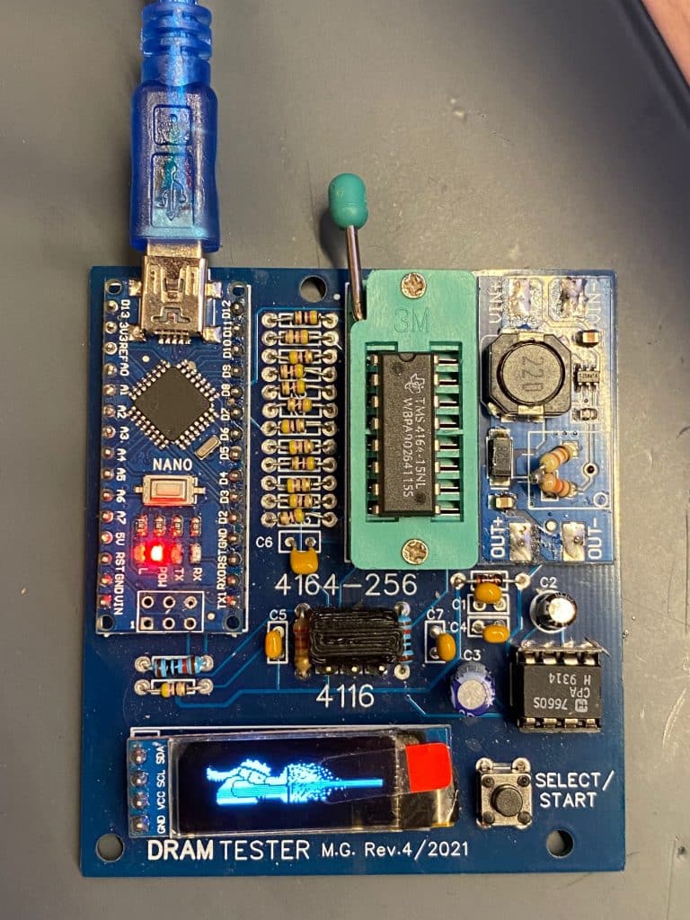
And finally version 4
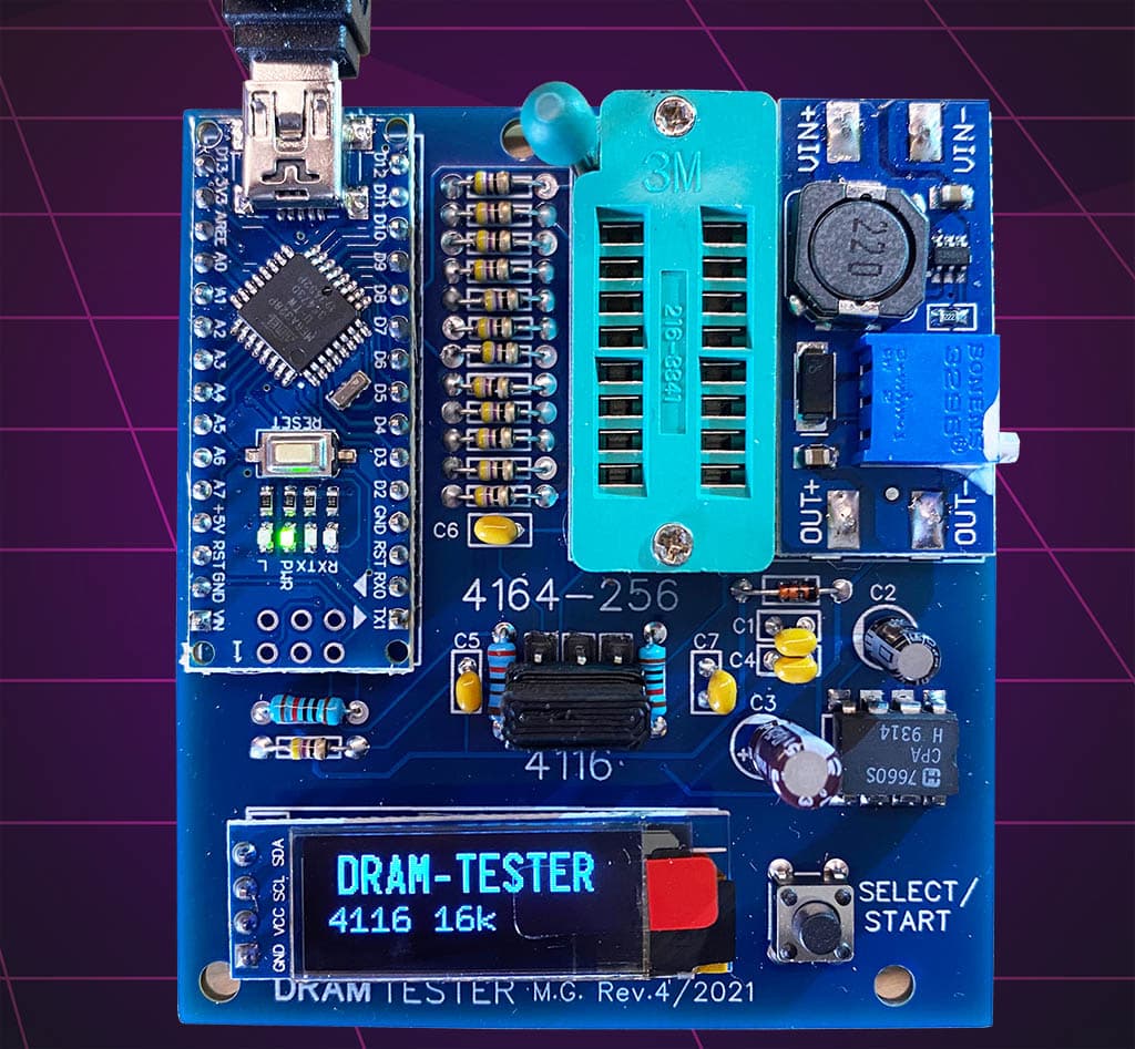
This uses the Arduino's power supply and elevates it to 12V with the booster, pin plus creates the -5V with the 7660.
The switch has been replaced with a jumper to avoid accidentally moving it and burning the ram, otherwise it is similar to version 3.
This PCB is also not compatible with the original source.
If you want to build it visit my github page
Beta testing version 4.2
non finisce qui, in test la versione software per testare anche le ram 4532 (parte alta o bassa), con finale animato! 🙂
This version runs 5 tests:
1 write-read bit 0-1
2 write-read all 1
3 write only all 1
4 read only all 1 expected (verify that data is retained)
5 write-read all 0