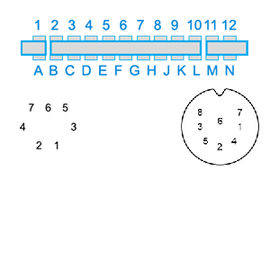
| Pin |
Signal |
Description |
Comment |
| 1 |
GND |
Ground |
(0 Volt) |
| 2 |
D0 |
data line 0 |
data bus of the computer |
| 3 |
D1 |
data line 1 |
| 4 |
D2 |
data line 2 |
| 5 |
D3 |
data line 3 |
| 6 |
D4 |
data line 4 |
| 7 |
D5 |
data line 5 |
| 8 |
D6 |
data line 6 |
| 9 |
D7 |
data line 7 |
| 10 |
/BLK 1 |
Memory block 1 |
Chip select for block 1; active-low, if address on bus is within $2000-$3FFF. |
| 11 |
/BLK 2 |
Memory block 2 |
Chip select for block 2; active-low, if address on bus is within $4000-$5FFF. |
| 12 |
/BLK 3 |
Memory block 3 |
Chip select for block 3; active-low, if address on bus is within $6000-$7FFF. |
| 13 |
/BLK 5 |
Memory block 5 |
Chip select for block 5; active-low, if address on bus is within $A000-$BFFF. |
| 14 |
/RAM 1 |
RAM 1 |
Chip select for RAM (memory area $0400 – $07FF) |
| 15 |
/RAM 2 |
RAM 2 |
Chip select for RAM (memory area $0800 – $0BFF) |
| 16 |
/RAM 3 |
RAM 3 |
Chip select for RAM (memory area $0C00 – $0FFF) |
| 17 |
V R/W |
VIC Read – /Write |
high during read cycle, low during write cycle of the VIC |
| 18 |
C R/W |
CPU Read – /Write |
high during read cycle, low during write cycle of the CPU |
| 19 |
/IRQ |
Interrupt Request |
Interrupt Request Line |
| 20 |
NC |
not connected |
| 21 |
+5V DC |
Supply Voltage +5V DC |
+ 5 Volt DC. |
| 22 |
GND |
Ground |
(0 Volt) |
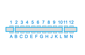
| A |
GND |
Ground |
(0 Volt) |
| B |
A0 |
address line 0 |
adress bus of the computer |
| C |
A1 |
address line 1 |
| D |
A2 |
address line 2 |
| E |
A3 |
address line 3 |
| F |
A4 |
address line 4 |
| H |
A5 |
address line 5 |
| J |
A6 |
address line 6 |
| K |
A7 |
address line 7 |
| L |
A8 |
address line 8 |
| M |
A9 |
address line 9 |
| N |
A10 |
address line 10 |
| P |
A11 |
address line 11 |
| R |
A12 |
address line 12 |
| S |
A13 |
address line 13 |
| T |
/I/O2 |
input/output 2 |
input/output area 2 ; active low, if address on the bus is within $9800-$9BFF. |
| U |
/I/O3 |
input/output 3 |
input/output area 3 ; active low, if address on the bus is within $9C00-$9FFF. |
| V |
SØ2 |
S Phi 2 |
system clock (1,108MHz for PAL, 1,018MHz for NTSC) |
| W |
/NMI |
non maskable interrupt |
Non Maskable Interrupt Line |
| X |
/RESET |
Reset |
If you pull this line to low, all chips will be re-initialized. The program counter of the CPU will be loaded with the reset-vector $FFFC and $FFFD (usually $FD22). |
| Y |
NC |
not connected |
| Z |
GND |
Ground |
(0 Volt) |















Commenti 2
peccato non trova la porta utente del vic20
Grazie della segnalazione, l’ho aggiunto.