Joystick C64 vs Joypad NES
Joystick and Joypad in comparison
Have you ever wondered how these pads work that with a few wires manage many buttons and directions while the classic Commodore or Atari joystick only had one button ?! Let's compare these two different technologies.

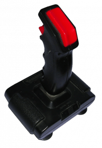
How can we forget the famous Quickshot, an ergonomic joystick but very easy to break.
In the past I have had several and I also tried to fix them but without success .. This model did not use microswitches but a small slightly curved metal plate that closed the contact under the pressure of the lever. The problem was just that, a great force was exerted and that little piece of metal was destroyed! Other joystick models were more robust but the technology was always the same, let's see in detail how they work.

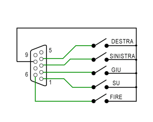
Simple isn't it? each button or direction is connected to a contact that closes towards GND, therefore a pin is required for each movement. This has the advantage of reading the status which will be very simple but will use a large number of gates. The great limitation of the Commodore Joysticks or generally Atari compatible was precisely that of having only one key, usually assigned to fire, while other functions such as jump or bombs had to be integrated with the keyboard or other combinations.
Is this so different?
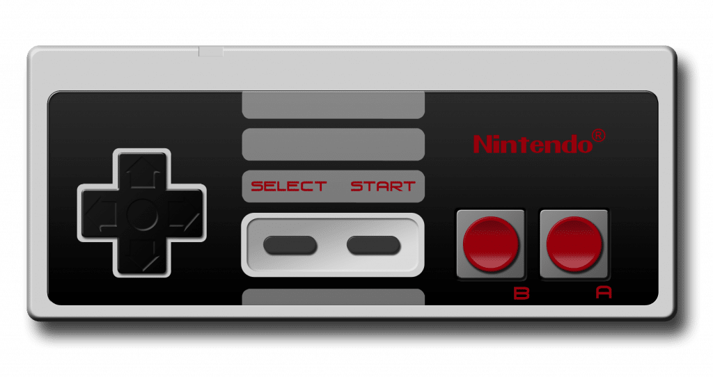
Apart from the shape, this pad has 4 directions and 4 buttons, one would think that as for the previous one, this too can use a cable for each function, already with 9 pins it would be possible.
This Joypad used by Nintendo is actually active with respect to the other that is content only with the switches, this has a chip that manages the 8 contacts and sends their status one at a time.
It converts 8 parallel inputs to 1 serial output, but how?


This is how it works, on the cable of this joypad we find 2 pins for the circuit power supply (5V) and other 3 pins named Latch, Clock, Data.
The pad will do nothing even if powered, we will go and interrogate it at certain intervals to understand the status of the buttons.
We need to send a 12us pulse on the Latch pin (active high) and then we can start sending a clock signal (normally high level) with a period of 6us (dutty 50%). The joypad will send on the Data line the status of the button / direction, in succession at each rising edge of the clock, so we can read them one at a time starting from the A key up to the -> direction. Button pressed = low level, not pressed = high level
Complicated?
No, the operation is simple, but it must be managed, not like the previous joystick, but with an integrated that several times per second will do this reading procedure.
The same thing applies to the Super Nintendo pad, only having more keys will send more data but the wires will be the same.

In this case the chip will send 16 states even if there are 12 keys in the pad, the last 4 states are always at a high level and not used in this system.
What if you want to connect the joypad of the NES or Super NES Commodore64?

If we connect the pad on this port, then we have to write a program to configure the pins used in inputs and outputs and manage the sending and receiving of data. Hard? well, it depends! writing it in basic is not complicated but as you can see from the video it is unusable, the interpreter takes too long to send and receive signals and even more to display them on the screen !!.
This is the code I wrote for this test: (luckily you don't need to have clocks and signals with precise timing!)
6 rem pb5: latch
7 rem pb6: date
90 dim l (15): print "S"
100 poke56579,40: rem pb3-5 output
110 poke56577.8: rem clock high
120 for x = 0 to1: next: rem pause
200 poke56577,40: rem latch on + clk
205 for x = 0 to 1: next: rem pause
206 poke56577.8: rem latch off
210 for x = 0 to 2: next: rem pause
220 x = 0
230 poke56577,0: for y = 0 to 1: next
235 l (x) = peek (56577): for y = 0to1: next
240 poke56577,8: for y = 0 to 1: next: x = x + 1
250 if x<16 then goto230
260 poke56577.8: rem clock high
270 print "s": for x = 0 to 15
280 if (l (x) and64) = 0 then print "*";
290 if (l (x) and64)> 0 then print "." ;: nextx
300 goto 200
READY.
While to be able to use it you need to tinker a bit with the assembler, this is the code I wrote for the example (from loc. $2000):
.C: 2000 A2 00 LDX #$00
.C: 2002 A0 00 LDY #$00
.C: 2004 A9 28 LDA #$28
.C: 2006 8D 03 DD STA $DD03
.C: 2009 A9 08 LDA #$08
.C: 200b 8D 01 DD STA $DD01
.C: 200e C8 INY
.C: 200f C0 FF CPY #$FF
.C: 2011 D0 FB BNE $200E
.C: 2013 A0 00 LDY #$00
.C: 2015 A9 28 LDA #$28
.C: 2017 8D 01 DD STA $DD01
.C: 201a C8 INY
.C: 201b C0 20 CPY #$20
.C: 201d D0 FB BNE $201A
.C: 201f A0 00 LDY #$00
.C: 2021 A9 08 LDA #$08
.C: 2023 8D 01 DD STA $DD01
.C: 2026 C8 INY
.C: 2027 C0 10 CPY #$10
.C: 2029 D0 FB BNE $2026
.C: 202b A0 00 LDY #$00
.C: 202d A9 00 LDA #$00
.C: 202f 8D 01 DD STA $DD01
.C: 2032 AD 01 DD LDA $DD01
.C: 2035 9D 00 21 STA $2100, X
.C: 2038 C8 INY
.C: 2039 C0 10 CPY #$10
.C: 203b D0 FB BNE $2038
.C: 203d A9 08 LDA #$08
.C: 203f 8D 01 DD STA $DD01
.C: 2042 A0 00 LDY #$00
.C: 2044 E8 INX
.C: 2045 E0 10 CPX #$10
.C: 2047 D0 DD BNE $2026
.C: 2049 A2 00 LDX #$00
.C: 204b BD 00 21 LDA $2100, X
.C: 204e 29 40 AND #$40
.C: 2050 C9 40 CMP #$40
.C: 2052 F0 08 BEQ $205C
.C: 2054 A9 2A LDA #$2A
.C: 2056 9D 00 04 STA $0400, X
.C: 2059 4C 61 20 JMP $2061
.C: 205c A9 2E LDA #$2E
.C: 205e 9D 00 04 STA $0400, X
.C: 2061 E8 INX
.C: 2062 E0 10 CPX #$10
.C: 2064 D0 E5 BNE $204B
.C: 2066 60 RTS

