
On this page we'll see how logic gates work: the basic functions computers use to carry out operations, and with which we can build our own electronic circuits.
Under each symbol you will find its truth table, which tells us how the gate’s output behaves depending on the various input signals.
Try it yourself by clicking on gates A – B and check the output of gate Q to see how it really behaves.
Once you understand how they work, you can build your own schematic by connecting them and testing them on this page.
How Logic Gates Work 💡
AND
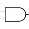
Truth Table
| TO | b | Q |
|---|---|---|
| 0 | 0 | 0 |
| 0 | 1 | 0 |
| 1 | 0 | 0 |
| 1 | 1 | 1 |
OR
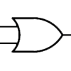
Truth Table
| TO | b | Q |
|---|---|---|
| 0 | 0 | 0 |
| 0 | 1 | 1 |
| 1 | 0 | 1 |
| 1 | 1 | 1 |
NOT (Inverter)
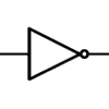
Truth Table
| TO | Q |
|---|---|
| 0 | 1 |
| 1 | 0 |
NAND
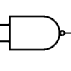
Truth Table
| TO | b | Q |
|---|---|---|
| 0 | 0 | 1 |
| 0 | 1 | 1 |
| 1 | 0 | 1 |
| 1 | 1 | 0 |
NOR
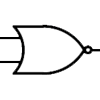
Truth Table
| TO | b | Q |
|---|---|---|
| 0 | 0 | 1 |
| 0 | 1 | 0 |
| 1 | 0 | 0 |
| 1 | 1 | 0 |
XOR
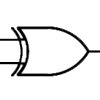
Truth Table
| TO | b | Q |
|---|---|---|
| 0 | 0 | 0 |
| 0 | 1 | 1 |
| 1 | 0 | 1 |
| 1 | 1 | 0 |
XNOR
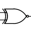
Truth Table
| TO | b | Q |
|---|---|---|
| 0 | 0 | 1 |
| 0 | 1 | 0 |
| 1 | 0 | 0 |
| 1 | 1 | 1 |
If you find gates on integrated circuits marked as Q̄ (note the bar above), it means the output is negated, i.e. it is inverted compared with how it would normally behave. In electronic schematics you may find these signals to indicate that a signal is negated or active low. Take an EPROM as an example: its Chip Enable pin (CE), which enables the memory, would by default be activated when the signal is high, i.e. 1 (5V in the case of a TTL signal). If instead the symbol has a bar above it, or the pin name is written as !CE or ~CE, it means that to activate that signal we have to give it an inverted signal, so the chip will be enabled when we supply a low signal, GND (0V).
If we look at the symbols of the various logic gates, we can see that some have a small circle on the output: this indicates that the output works the other way round, i.e. it is negated, so if according to the symbol the output should be 0, it will be driven to 1 and vice versa, exactly as if a NOT gate were connected after the output.
All these logic gates can be cascaded to form a circuit able to count or store data (with the help of a flip-flop).
