Enterprise 64 Video Fix
Let's see how to fix the Enterprise 64 or 128 with a black screen.
Remember that it is a delicate process, you must always be careful not to damage your computer, take your time.
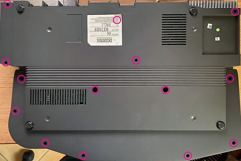
First we remove the screws at the bottom

Then we proceed to remove the keyboard (only the membrane will remain) and then the upper cover, taking care not to bend the flats of the membrane too much and to remove it from the connectors by hanging it just above the connector to avoid applying too much force on the flat. These membranes tend to harden over time and become brittle, so if we bend it too much it can break or cracks can form, the problem is that the conductors pass over this material and therefore if cracks are formed they no longer conduct. In case you can find new membranes or if the damage is not very serious you can try the repair with a conductive ink to rebuild the track.
Now we have arrived at the motherboard, held with only 2 screws, let's remove them to be able to detach it and work easily.

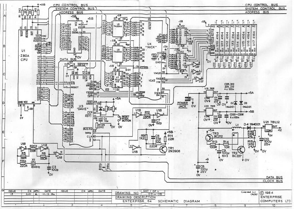
Now we will also need the diagram to understand where to start checking!
Let's start checking the voltages on the 5V (we have 2: 5A and 5B)
we continue with the voltage, we must have a 12V output at the 78L12, if you find this low voltage (about 7-8V) it means that the circuit to raise the voltage does not work, check the input of the 78L12 and you should have about 19V otherwise the circuit does not work (this was my case).
If the circuit does not actually raise the voltage, it is necessary to check the capacitor C9 (100uF) and the transistor TR2 which is the most subject to breakage given its position.
In my case I had to replace TR2 and the capacitor, indeed I replaced them all because they were all with a high resistance (not one was saved!).
If the voltage is OK, proceed to check the other components and signals, first check the presence of the clock on U18 at pin 12, there should be a square wave of 8Mhz, in pin 4 one of about 4Mhz.
In case you feel with your finger if you detect a chip that gets too hot, the video chip is normal for it to heat up, the Z80 and the ROM (U2) are little more than warm after 8-10 minutes.
Then check the clock signals on the Z80 (pin 6) the CE / RD (20,22) of U2, activity on the bus and RAM.
There are several buffers and logic gates around, in case check the input and output signal of the gates to see if it meets what it is designed for.
In my case I replaced a 74LS32, 74LS86,74LS244 for a problem on the synchronism of the RGB signal but it didn't help and in fact, testing the replaced chips, I found no problems.
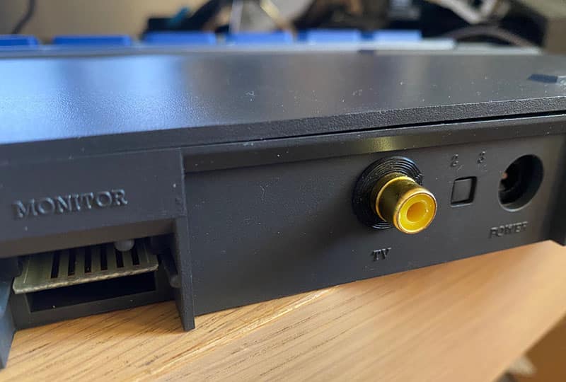
If you want to have a composite signal instead of the RF signal of the modulator, it is necessary to make the modification with a scheme that is found on the network and only requires the use of a BC182 transistor and little more.
Go to the next section for the schematic and connections.
Composite mod
This is the simple scheme found on the net to take the composite signal from the computer.
I noticed that with this mod on white you get a slightly distorted signal but I can't do any further tests for now because I don't have the possibility to load programs or games on this machine.
I hope to find an SD card reader soon that I can use to load programs
For now I'm happy to write something and to be able to test it on my monitor. I ordered a cable to be able to connect it via RGB signal, then I will do further tests.


