If you want to connect your Atari 2600 or 7200 to a modern device you will need to make a small modification to the console to be able to use the composite signal instead of the native RF signal of these models.
WarningThe modification is not difficult but it requires a bit of manual skill in unsoldering some components and building the circuit for the modification.
As usual I must warn you that we do not take any responsibility and therefore if you are not sure .. do not do it!
What do you need?
We will need the circuit for the modification, we can build it ourselves or take it already built.
A welder.
A tin sucker or a desoldering braid, better if you have an electric desoldering iron.
At least 2 female RCA connectors (3 is recommended for left and right audio channel and video) to be able to connect and disconnect the console easily but if you prefer you can internally solder the video cable without connectors.
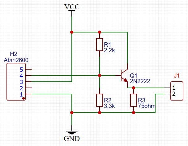
2600-7800 schematic
ATARI 2600 The pinout in this figure is the RF modulator connector on the 2600 version. GND is on pin 1, 5V is on pin 3 and the video signal is on pin 4. In the diagram, the Vcc and GND signals represent only the levels that we have on the pin.
The resistor R3 is optional, if you see that you have the video signal too high then insert it to attenuate the level.
ATARI 7800 The diagram is the same but the pinout of the connector is different, on this version we have the GND on pin 1, the 5V on pin 2 and the video on pin 3.
PS. The audio part is not in the circuit, you just need to take the signal with a wire and bring it to its connector, you will see later how.
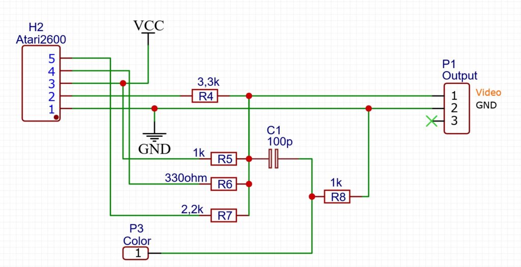
2600JR schematic
The Junior version is totally different, I left the connector on the schematic to facilitate pin mapping but in reality on this model we do not have the removable modulator block and therefore no connector to use.
Installation
Open your console by removing the screws on the bottom, if you have the 2600jr model be careful because it has plastic clips in the thinnest part that must be widened (trying not to break them) from the ventilation grille and has a flat cable for the buttons.
For the 2600 and 7800 versions, the modulator must be removed, for all versions, if you want a cleaner signal, some components must be removed.
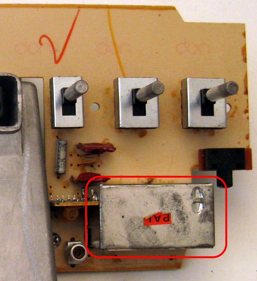
Atari 2600 PAL (4 switches)
Very common version of the Atari 2600, once the case has been opened, the tabs that hold the metal screen must be lifted and removed to access the components. When you then reassemble it, pay attention to the audio signal cable, just do not squeeze the tabs near the cable in order to keep the screen slightly raised.
Remove the following components:
Q201 (or Q202), L201, R222, R209 (or C209)
* if you want to put everything back as it was one day, I advise you not to remove them completely but to raise one lead of the resistors and capacitors. For the transistor, if you do not want to remove it completely, just raise its collector, while for the inductance which, being rigid, must still be removed but it can be attached to the pcb or the case with insulating tape so as not to lose it.
On some boards, the components may be slightly different.
Removed the components you can take the audio signal on the 1k resistor near the capacitor (yellow circle) and take it directly to the RCA connector. For convenience of connections, two RCA audio connectors (right and left) should be used connected to the same signal, so by connecting the cable to the TV we will have a mono signal, but we will hear it on all speakers instead of only on one side. From the modulator connector, pins 1 (GND), 3 (+ 5V), 4 (Video) must be taken and connected to the amplifier board and from there the video signal will be taken to the RCA connector.
I used a board already prepared for the Atari 2600 pinout so that it could be soldered directly in place of the modulator avoiding other wires.
Atari 2600 PAL (6 switches)
Modulator to be removed on the pcb levers ->
In this version the following components must be removed:
R209, Q202, L201, R216
The audio signal must be taken on the R209 resistor (sign highlighted in yellow), while the video and power signals must be taken from the pcb where the modulator has been removed (same pinout as the 4 switch version).
On this model it is probably not possible to directly solder the board to the pcb due to the metal shield very close, in case it is advisable to use wires to connect the board.
The rest is as for the previous version, bring the audio and video signals to the connectors and close everything!.
* Always be careful to pass the audio cable without squeezing it too much under the metal shield.
Atari 2600JR without and with PAL modulator
On this version the following components must be removed:
Q4, L6, R56, C33, R17
On this version the following components must be removed:
Q4, L8, R56
Attenzione, questa è la modifica da usare con la mia scheda. For both versions the following signals are then taken and brought to the board to mix the signal.
For convenience i will re-publish the schema and there i map the pins. Pin1 of the board goes to GND (photo Atari) 2 goes to the resistance labeled N.2 the 3 goes on the pin labeled 15 the 4 on the number 12 5 on number 10 the color signal goes to the resistance labeled color the audio signal (purple circle) can be brought to the RCA connectors
The rest is always the same as the previous versions, the video signal will come out from the card and it will be brought with wires to the RCA connector.
La modifica generica da costruire se non usate la mia scheda è questa che trovate sul sito console-corner.de
Atari 7800 PAL
On this version the following components must be removed:
L6, R32, R33, R62, Q8
the audio signal can be taken from the right pins of the R33 and R32 resistors, join them and take them to the RCA connector (see photo below).
The pinout of the modulator we removed is not the same as the Atari 2600 version but is the following: 1: GND 2: + 5V 3: Composite video
If you are using the board seen previously, just shift the pins by one position, then use a 3-pin header starting from pin #2 of the board (so on the board we will have soldered pads 2,3,4 starting from the left). We make a bridge with the tin between pin1 and 2 of the board (so the GND of the board will be present at pin 2 which however is not used on the mod for the 2600 version) So now we can solder the board directly to the Atari pcb using pins 1,2,3 of the old modulator.
If you do not use this board, just bring the relative signals of the pcb to the circuit you have built or bought, in the diagram in the figure for example: pin 1 is the GND (goes to pin 1 Atari), 3 is + 5V (goes to pin 2 Atari), 4 is video (goes to pin 3 Atari).
Once again as mentioned above, we bring the audio and video signals on the RCA connectors to finish the modification.
Hi. Thanks for the tutorial. I followed it and it works but i only see video in black and white, no matter which game i play or how i connect it to the tv (i even tried a crt tv)
Hello, all the mods that are on this page are for PAL consoles, I’ve never tried on an NTSC one.
I advise you to take a look at this which seems to have modified one: https://www.youtube.com/watch?v=hYQi6r2mje8
Thanks for your interest.
No, the modification does not have any potentiometer. What you see in the cards is a coil to regulate the frequency of the RF signal which, with the modification by removing the transistor etc. is disabled
Could you explain the functions of pins 1 and 2 on the J1 connector?
Also, why does the image make it look like the black wire coming from pin 1 of the J1 connector is on a trace leading all the way to the IC (integrated circuit), without clearly indicating where it should be connected?
Potete spiegarmi quali sono le funzioni dei pin 1 e 2 del connettore J1?
E perché nell’immagine sembra che il filo nero che esce dal pin 1 del connettore J1 sia su una pista che porta fino all’integrato senza che sia indicato chiaramente dove collegarlo?
Hai ragione, ho corretto lo schema. Al tempo avevo preso la parte del circuito della mia scheda che può fare entrambe le versioni e mancava il GND e non era completo lo schema. Ora ho caricato la parte solo 2600jr corretta. Il connettore era a 3 poli per prevedere anche l’audio ma non serve, basta prendere il segnale audio dal pcb del 2600 e portarlo sul connettore audio senza passare per la scheda che non aggiunge nulla.
We use cookies strictly necessary to ensure an optimal experience in browsing the site. By clicking on "Accept all", you allow us to use all cookies. You can always review your consent by clicking on Cookie settings. We use cookies on our website to give you the most relevant experience by remembering your preferences and repeat visits. By clicking “Accept All”, you consent to the use of ALL the cookies. However, you may visit "Cookie Settings" to provide a controlled consent.
This website uses cookies to improve your experience while you navigate through the website. Out of these, the cookies that are categorized as necessary are stored on your browser as they are essential for the working of basic functionalities of the website. We also use third-party cookies that help us analyze and understand how you use this website. These cookies will be stored in your browser only with your consent. You also have the option to opt-out of these cookies. But opting out of some of these cookies may affect your browsing experience.
Necessary cookies are absolutely essential for the website to function properly. These cookies ensure basic functionalities and security features of the website, anonymously.
Cookie
Durata
Descrizione
cookielawinfo-checkbox-analytics
11 months
This cookie is set by GDPR Cookie Consent plugin. The cookie is used to store the user consent for the cookies in the category "Analytics".
cookielawinfo-checkbox-functional
11 months
The cookie is set by GDPR cookie consent to record the user consent for the cookies in the category "Functional".
cookielawinfo-checkbox-necessary
11 months
This cookie is set by GDPR Cookie Consent plugin. The cookies is used to store the user consent for the cookies in the category "Necessary".
cookielawinfo-checkbox-others
11 months
This cookie is set by GDPR Cookie Consent plugin. The cookie is used to store the user consent for the cookies in the category "Other.
cookielawinfo-checkbox-performance
11 months
This cookie is set by GDPR Cookie Consent plugin. The cookie is used to store the user consent for the cookies in the category "Performance".
viewed_cookie_policy
11 months
The cookie is set by the GDPR Cookie Consent plugin and is used to store whether or not user has consented to the use of cookies. It does not store any personal data.
Functional cookies help to perform certain functionalities like sharing the content of the website on social media platforms, collect feedbacks, and other third-party features.
Performance cookies are used to understand and analyze the key performance indexes of the website which helps in delivering a better user experience for the visitors.
Analytical cookies are used to understand how visitors interact with the website. These cookies help provide information on metrics the number of visitors, bounce rate, traffic source, etc.
Advertisement cookies are used to provide visitors with relevant ads and marketing campaigns. These cookies track visitors across websites and collect information to provide customized ads.


6 Comments
Hi. Thanks for the tutorial. I followed it and it works but i only see video in black and white, no matter which game i play or how i connect it to the tv (i even tried a crt tv)
Hello, all the mods that are on this page are for PAL consoles, I’ve never tried on an NTSC one.
I advise you to take a look at this which seems to have modified one: https://www.youtube.com/watch?v=hYQi6r2mje8
Thanks for your interest.
Have you tried to adjust the potentiometer after your composite mod?
No, the modification does not have any potentiometer. What you see in the cards is a coil to regulate the frequency of the RF signal which, with the modification by removing the transistor etc. is disabled
On Atari 2600Jr without RF module
Could you explain the functions of pins 1 and 2 on the J1 connector?
Also, why does the image make it look like the black wire coming from pin 1 of the J1 connector is on a trace leading all the way to the IC (integrated circuit), without clearly indicating where it should be connected?
Potete spiegarmi quali sono le funzioni dei pin 1 e 2 del connettore J1?
E perché nell’immagine sembra che il filo nero che esce dal pin 1 del connettore J1 sia su una pista che porta fino all’integrato senza che sia indicato chiaramente dove collegarlo?
Hai ragione, ho corretto lo schema. Al tempo avevo preso la parte del circuito della mia scheda che può fare entrambe le versioni e mancava il GND e non era completo lo schema. Ora ho caricato la parte solo 2600jr corretta. Il connettore era a 3 poli per prevedere anche l’audio ma non serve, basta prendere il segnale audio dal pcb del 2600 e portarlo sul connettore audio senza passare per la scheda che non aggiunge nulla.