

Philips Videopac+ G7400 black screen
16 May 2024
PicoZX
25 July 2024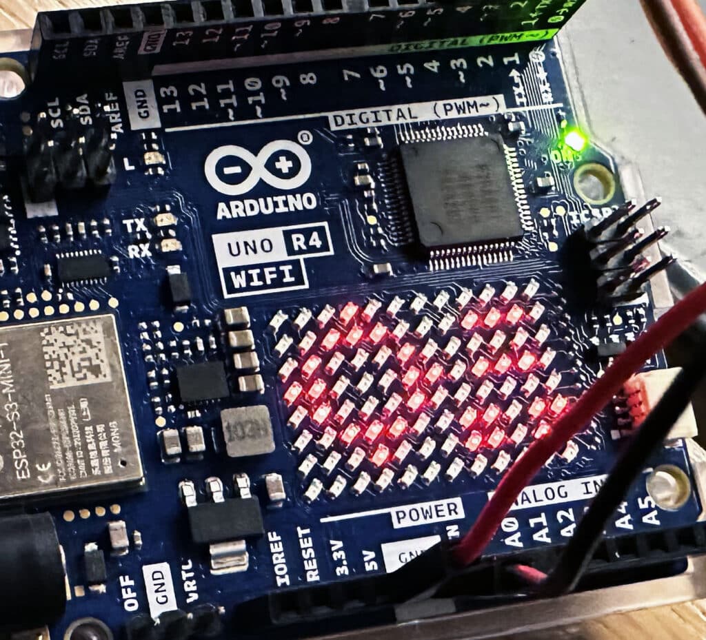
With the repair of a NES Advantage joystick, let’s see how to build a tester for this system and how it works.
For the project I used an Arduino R4 WiFi, why?
Well, we don’t actually need the networking feature, but it’s handy because it has a small LED matrix display that can show us the state of the buttons without having to add external LEDs or other displays.
A quick recap.
As I said in a video, the classic, much-copied Atari joystick uses one pin for each direction/button; this pin is closed onto a common contact that is usually connected to GND. The advantage is having all the buttons and directions immediately available for reading; the downside is the large number of wires. In fact, classic DB9 joysticks only had one button, partly because when it was designed games weren’t that advanced and one button was more than enough.
The more modern NES/SNES system instead sends all the buttons and directions serially. An excellent system that uses only 5 wires (power included) but can handle many more buttons. The downside is that, being a serial read, it takes a bit longer to receive all the button states (negligible if the reads are done quickly and continuously).
The protocol
Unlike the classic, much-copied Atari joystick, which uses one pin for each direction/button that is closed onto a common wire usually connected to GND, the NES joypad/joystick uses serial communication.
The advantage? Well, having all the buttons and directions on separate wires makes any state immediately available for reading, but the downside is the large number of wires needed to handle them all.
The more modern NES/SNES system instead sends all the buttons and directions serially.
An excellent system that uses only 5 wires (power included) but can handle many more buttons.
The downside is that, being a serial read, it takes a bit longer to receive all the button states (negligible if the reads are done quickly and continuously).

Alongside, the pinout of the NES joystick port.
As you can see, only a few wires are connected; pins 6/7 are not used by standard controllers.
To request the state of the joypad, we’ll use Clock and Latch to receive the data from the Data pin.
Obviously we also need to supply power to the joystick.
But how many buttons does a NES joypad have?

4 buttons and 4 directions, for a total of 8 inputs to handle.
As you can guess, that’s just about enough for a DB9 if we count the common wire used to close the contact.
But if we did it that way, we couldn’t add a power wire to handle auto-fire or LEDs, and if we wanted to add a button there would be no room left! In fact, the SNES controller has a whole 4 extra buttons!! But the same pins, albeit with a different connector.
Now let’s see how to read these buttons using 3 wires.
Inside the joystick/pad there is a shift register that reads the state of the buttons and directions and sends them out on the data pin, one at a time, clock after clock.
Let’s start reading: we drive the Clock and Latch pins ourselves and keep them low; the Data pin is set by the shift register and there we find the button state, high with the button not pressed, low with the button pressed.
First step (start): we send a pulse on the Latch pin, the controller stores the state of the buttons/directions and sets its data output to the state of the first button (button A).
Second step: we read the other data, sending a pulse on the Clock pin, and on the Data pin we’ll find the next button (button B).
Got it? Well, I think so.. By sending further clock pulses, all the other states are read in sequence.
The complete reading sequence is as follows:
A – B – START – SELECT – UP – DOWN – LEFT – RIGHT
Once we reach the last direction (7 clocks), we need to send a Latch pulse to restart the sequence.
So: (Latch) -> button A -> Clock -> button B -> Clock -> Start button … up to the right direction, then we start again with the Latch.
The TESTER
Now that we know exactly how it works, let’s write the Arduino sketch.
I used pin 2 as Clock, 3 as Latch and 4 as Data, plus a small animation at start-up.
					#include "Arduino_LED_Matrix.h"
ArduinoLEDMatrix matrix;

#define nData 4
#define nClock 2
#define nLatch 3

const uint32_t joy[] = {
		0x10038e44,
		0xc6e4403,
		0x9b11b000,
		66
};
const uint32_t r[] = {
		0x3f02182c,
		0xc2cc2182,
		0xd82ac398,
		66
};

void setup() {
  pinMode(nData, INPUT_PULLUP);
  pinMode(nClock, OUTPUT);
  pinMode(nLatch, OUTPUT);
  digitalWrite(nClock, LOW);
  digitalWrite(nLatch, LOW);
  matrix.begin();
  matrix.loadFrame(joy);
  delay(1000);
  matrix.loadFrame(r);
  delay(1000);
}

void loop() {
uint8_t  frame[8][12] = {
  { 0, 0, 0, 0, 0, 0, 0, 0, 0, 0, 0, 0 },
  { 0, 0, 0, 0, 0, 0, 0, 0, 0, 0, 0, 0 },
  { 0, 0, 0, 0, 0, 0, 0, 0, 0, 0, 0, 0 },
  { 0, 0, 0, 0, 0, 0, 0, 0, 0, 0, 0, 0 },
  { 0, 0, 0, 0, 0, 0, 0, 0, 0, 0, 0, 0 },
  { 0, 0, 0, 0, 0, 0, 0, 0, 0, 0, 0, 0 },
  { 0, 0, 0, 0, 0, 0, 0, 0, 0, 0, 0, 0 },
  { 0, 0, 0, 0, 0, 0, 0, 0, 0, 0, 0, 0 }
};
  digitalWrite(nLatch, HIGH);
  digitalWrite(nLatch, LOW);
  if (digitalRead(nData) == LOW) {
    frame[6][11] = 1;
    frame[6][10] = 1;
    frame[5][11] = 1;
    frame[5][10] = 1;
  }
  digitalWrite(nClock, HIGH);
  digitalWrite(nClock, LOW);

    if (digitalRead(nData) == LOW) {
    frame[6][8] = 1;
    frame[6][7] = 1;
    frame[5][8] = 1;
    frame[5][7] = 1;
  }
  digitalWrite(nClock, HIGH);
  digitalWrite(nClock, LOW);

    if (digitalRead(nData) == LOW) {
    frame[1][10] = 1;
    frame[1][9] = 1;
    frame[1][8] = 1;
  }
    digitalWrite(nClock, HIGH);
    digitalWrite(nClock, LOW);

    if (digitalRead(nData) == LOW) {
    frame[3][10] = 1;
    frame[3][9] = 1;
    frame[3][8] = 1;
  }
    digitalWrite(nClock, HIGH);
    digitalWrite(nClock, LOW);

    if (digitalRead(nData) == LOW) {
    frame[0][3] = 1;
    frame[1][2] = 1;
    frame[1][3] = 1;
    frame[1][4] = 1;
  }
    digitalWrite(nClock, HIGH);
    digitalWrite(nClock, LOW);

    if (digitalRead(nData) == LOW) {
    frame[6][3] = 1;
    frame[5][2] = 1;
    frame[5][3] = 1;
    frame[5][4] = 1;
  }
    digitalWrite(nClock, HIGH);
    digitalWrite(nClock, LOW);

    if (digitalRead(nData) == LOW) {
    frame[3][0] = 1;
    frame[4][1] = 1;
    frame[3][1] = 1;
    frame[2][1] = 1;
  }
    digitalWrite(nClock, HIGH);
    digitalWrite(nClock, LOW);

    if (digitalRead(nData) == LOW) {
    frame[3][6] = 1;
    frame[4][5] = 1;
    frame[3][5] = 1;
    frame[2][5] = 1;
  }

matrix.renderBitmap(frame, 8, 12);
delay(10);
}
You can copy the code, paste it into an Arduino sketch and upload it to the R4 WiFi version; if you want to adapt it without using the display, for other Arduino versions (such as the Nano, Micro etc.) you can modify the code by removing the Matrix display part.
Patreon users can download the file from the download page or at this link
Operation
Now let’s see how the tester for the NES joystick/pad works

I drew the buttons and directions on the Matrix display as they appear on the Advantage joystick. This screen is shown as soon as the Arduino is switched on and disappears shortly after. When pressing a button or a direction we should see the corresponding symbol appear on the display; if not, there’s a problem in the joystick/pad, perhaps a dirty contact, a solder joint or a broken trace..
In the worst cases the shift register might have failed too, nothing expensive or complicated to replace; it isn’t socketed but it can be desoldered easily.
Below is our Arduino with the program loaded, as it looks at start-up.
The only thing we’ll need to do a tidy job is a female NES connector, so we can plug in the joystick/pad without having to use flying wires pushed into the pins of its connector.

And here is the video of the NES Advantage joystick repair and the making of the tester.
Remember that to support our work you can subscribe to the channel; it’s free and it’s a nice way to say thank you.
If you’d like to join Patreon, here is our link: patreon.com/retrofixer

similar posts