VIC20 diagnostic card
30 July 2022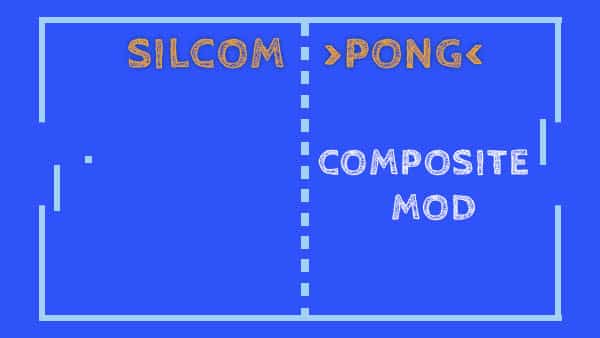
Silcom pong in composite
13 August 2022You would like to make it yours
C16 or C116 as a Plus 4?
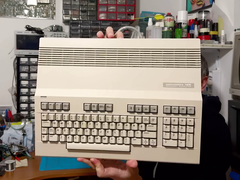
Compared to the Plus4, the Commodore 16 can address up to 16Kb of RAM, but if we look at the computer diagram we will see that it is not very different from the Plus4 which instead uses 64, let's see why.
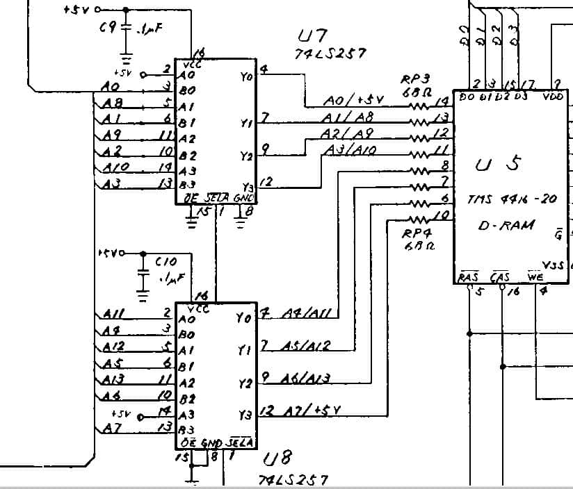
Taking a look at the scheme of these machines, it immediately catches the eye that in the C16 the memory addressing has 14 addresses instead of 16 in the Plus4, it is obvious why the RAM used (2x TMS4416) only needs these lines.
So to increase the memory just change the two RAM with 4464 and add the missing addresses !.
The only thing is that the multiplexers (74LS257) that manage the addresses, have 2 pins to the positive (Pin2 of U7 and Pin14 of U8).
If we don't want to cut the track to bring us the correct signal, we have to come up with something, and here is that something.
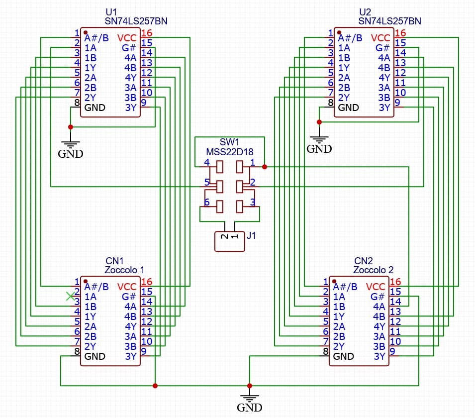
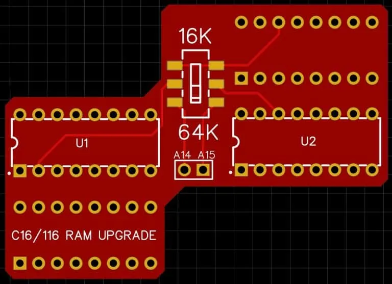
A simple adapter to insert above the 74LS257, alternatively a single adapter could have been made for each multiplexer but there would have been more wires around and the possibility of excluding the expansion would have been split on the two PCBs.
This scheme does nothing but bring the signals of U7 and U8 on the multiplexers and with the switch we can add the inputs A14 and A15 that were missing, or leave everything original as before.
Beyond this, as mentioned above, the 2 RAM banks will have to be replaced with the 4464 and that's it.
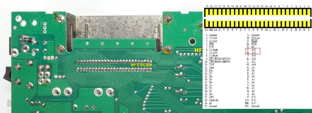
But where do I get the missing addresses?
Now all that remains is to bring those two signals to the multiplexers and that's it!
Watch the video to see the construction and installation of this card.
The project can be downloaded from my GitHub page:
64K expansion without soldering!
It doesn't end there, if we don't want to unsolder components on the board, there is another way to expand the memory.
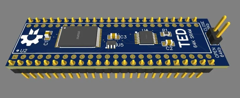
The secret was TED!
In the C16 coprocessor we find all the signals we need because the latter also manages the memory.
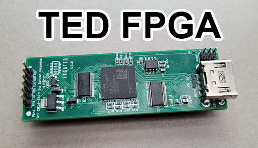
So we could inhibit the RAM control on the card and bypass it with our memory, once again we need an adapter to be inserted between the TED and the computer socket.
Below is the diagram of what has been said, the SRAM obtains the addresses from the computer and if the expansion is active (selectable by jumper J1) it reads the memory timing (CAS) and manages the DB0-7 outputs.
If the jumper is inserted, the card remains disabled and the CAS signal will manage the original computer memory.
This card is easier to install but more difficult and expensive to build, in addition if we have the old type socket in the computer with only one pin on each side, this will get too wide by inserting the adapter and will be unusable if we want to lose the TED. The solution is to use a second socket to be interposed between the board and the socket of the C16 or unsolder that old socket, often the cause of false contacts and malfunctions, replacing it with a better one, perhaps with turned pins so that you can put on and remove it. the card without problems.
https://www.pcbway.com/project/shareproject/Commodore_16_RAM_expansion_64Kb_solderless_on_TED_514ba3fc.html
The project can also be downloaded from my GitHub page:
https://github.com/zeus074/Commodore16-TED-RAM-Expansion
If you are not subscribed to the YouTube channel, you can do it here:


