Here we are with another great computer, the Commodore 128. One of my favourites from Commodore. A friend of mine had one and yes, we always played in 64 mode, but it looked great and gave the impression of something big and professional. In fact it was, since it was three computers in one. Shame there was hardly anything for 128 mode, and we didn’t even know what CP/M was.
I bought one several years ago, you can find it among my repairs; unfortunately it was yellowed and I had to retrobright it. All lovely just after doing it, but after a year you could already see the inevitable return of the yellow! Now I can tell you that 5 years on it’s back to how it was, so I’ve stopped wasting time with retrobright, because you risk damaging the plastic both in colour and in strength, and it goes back to how it was anyway. I don’t know if there’s a product you can apply to prevent yellowing or to preserve it for longer.
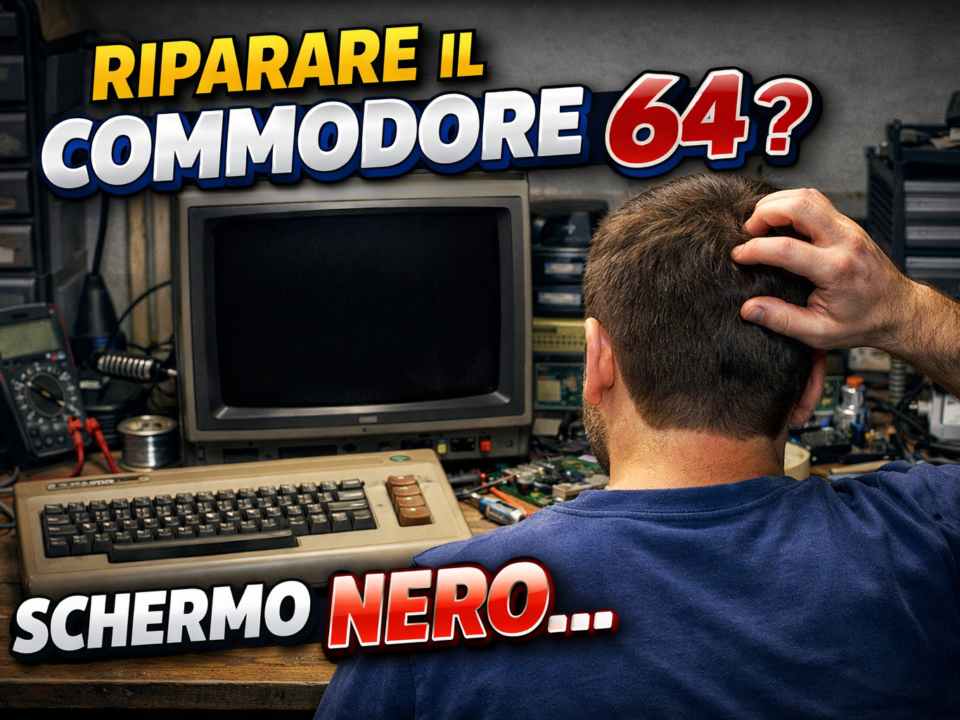
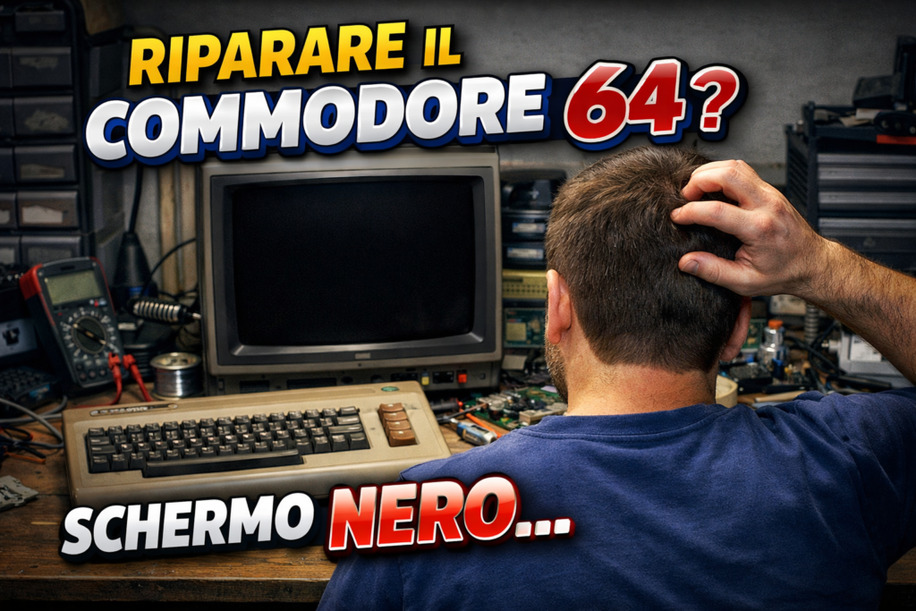
That said, I found a lovely example: cosmetically it looks new, no scratches, and white! But all that glitters is not gold: in fact it doesn’t work, it gives a nice black screen, which, as on the C64, could be anything.
Let’s see how the 128 is made. The photo already shows how complex it can be. I tried a Dead Test cartridge, which, being compatible with 64 mode, can give us indications about faulty RAM, even though here we have 2 banks of 64K. In case of flashes we can test both the upper and the lower bank. Even with the Dead Test I get a nice black screen, which doesn’t tell us much except that the problem might be somewhere else, before we can check the RAM.
On these computers we often find memory chips marked MT, a bit like the logic chips marked MOS; these are the first to keep an eye on because of their reputation for failing.
This is an excellent starting point, given the many processors that work together to run the computer. As with any repair, you need to start with the basics and take nothing for granted, so let’s check the voltages, the clock on the various CPUs and the reset signal.
Here I noticed that on one clock of the video processor I had 1MHz, while the guide said 2MHz and, if that wasn’t the case, to check the C128’s processor. I hadn’t checked whether my working computer was the same or actually had 2MHz, because otherwise we’ve already found one fault, the 8502 processor, since the guide gives the VIC-II (U21), the CPU (U6) or the MMU (U7) as possible faults.
For now let’s carry on investigating. I checked the RAM, since it was all socketed... A disaster! All the upper RAM chips were faulty, but that wasn’t all: some in the lower bank had problems too. OK, replaced all the dead ones. Still a black screen. In the meantime I also look into the socketed chips that I can test in my working 128, and find that the CIAs, the VICs and the MMU are good.
With the oscilloscope on the RAM signals, here’s the first problem: some signals are missing, so I set about checking with the multimeter all the lines that have to reach all the memory chips, et voilà!
I remove the socket and discover that a real mess has been made underneath. When desoldering the RAM chips they ripped off several traces; some were repaired, but others are still broken. Now, with plenty of patience and blessings for whoever does this kind of work, I set about removing all the sockets with trace problems. There are at least 3 that need checking and their connections redoing. And here comes my usual sermon: “if you can’t desolder a component, don’t force it: either use hot air or leave it alone”. Not that you can’t do damage with hot air, on the contrary, you can see some real horrors there too, but using the right desoldering temperature, once the PCB and the pins of the chip to be removed have heated up, it comes away easily without forcing it and tearing off the traces. Obviously you need to remove as much solder as possible with a desoldering station or, at worst, a decent solder sucker.
We’re nearly there. Once all the RAM lines have been restored, I check the signals on the CPU (8502) and see there’s no activity on the RDY pin, which should signal when it’s ready to receive data. OK, let’s desolder the CPU and try the one from my working 128.
Finally a screen we like, but now for the nasty surprise of this repair.
Replacing all those RAM chips isn’t a big problem because they’re cheap; the bigger problem is the 8502, which isn’t exactly inexpensive. In this case, since I didn’t pay much for the machine and given its overall condition, it was worth it, but this should make us think when we find a faulty computer: sometimes it could be something trivial, but it could also be something expensive, and if the starting price isn’t low already, we risk paying more than for a working one. This is often true for the 264 series, where the parts can cost more than the machine.
Watch the whole repair to see how much work it took to fix this computer