CDI 450 TimeKeeper fix
16 January 2022
Atari C380 video pinball composite mod
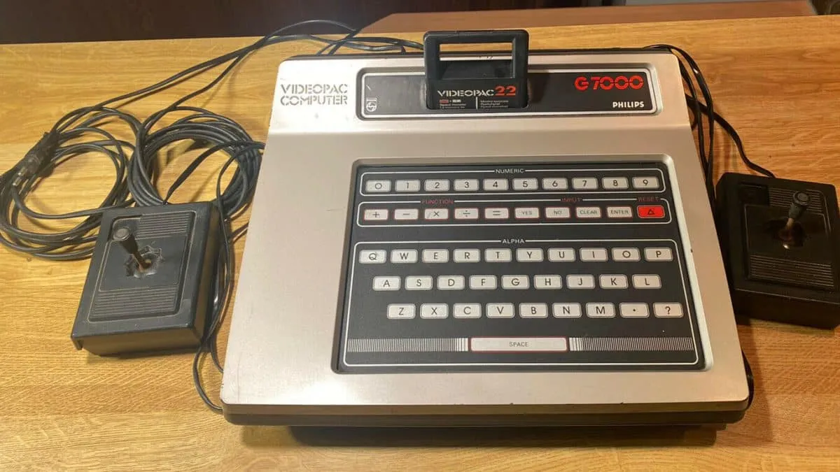
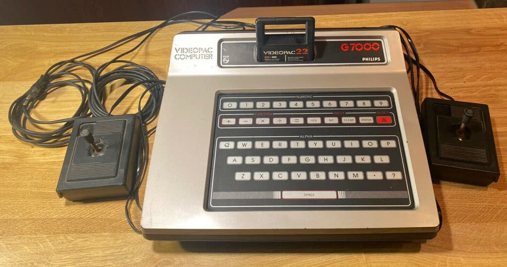
22 February 2022In this article we see how the Philips G7000 videopac and its restoration is done.
This console has been produced since 1978 in Europe while in America it was called Magnavox Odyssey2.
Equipped with an Intel 8048 microcontroller running at 1.79Mhz with a coprocessor for graphics with sprite management, 4 customizable (8x8px) and 12 in the internal library, all monochrome and the displayable colors were 8 chosen from a palette of 16 colors.
Well, I could not leave this beautiful console so semi-destroyed, I took it little by little with a game and general conditions to test, the joysticks were in very bad shape!
But let's not get discouraged ..
Let's first start to test if we have an RF signal, already this console only comes out with this video signal ..
Well, nothing, just fog and a few small hints of a carrier.
Smontiamo tutto e vediamo cosa troviamo al suo interno, un po’ come gli ovetti Kinder 😀
The main board is connected directly to the 5V power supply without connector, by measuring the voltage I check that the power supply is perfect, the problem is in the motherboard or in the modulator. Beware of the signals that go to the modulator, they use non-standard colors and can easily mislead us. However I have not found a composite signal, let's go on with the analysis and cleaning!
Luckily there is a nice repair manual with the integrated signals too, I leave you the link if you need it
After a good cleaning I see a socket that I don't like, it is one of those that makes contact only with the external part of the integrated and I decide to replace it, indeed since there are only 3 in total, I change them all.
Here is the first problem!
The socket had the pins eaten by the oxide, in fact, while I was unsoldering it 7 of these broke off.
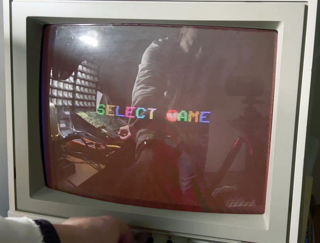
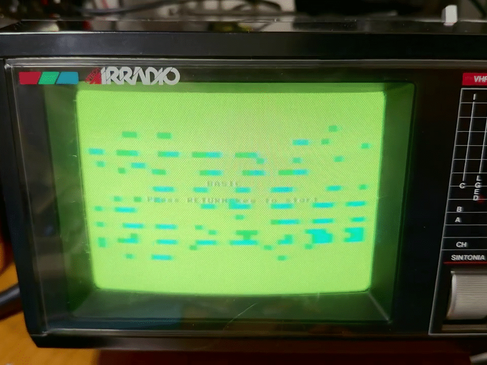
After replacing the sockets, I immediately do a test trying to take the composite signal before the modulator .. and Magic! SELECT GAME appears
Obviously it is out of sync and is not visible due to the low signal, but now if we try to amplify it we should have a perfect composite signal.
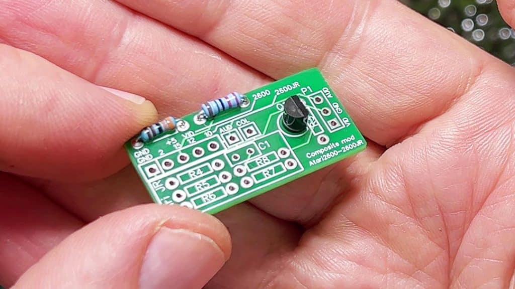
Composite MOD
The modification is like the one used in the Atari 2600, below the article if you need it.
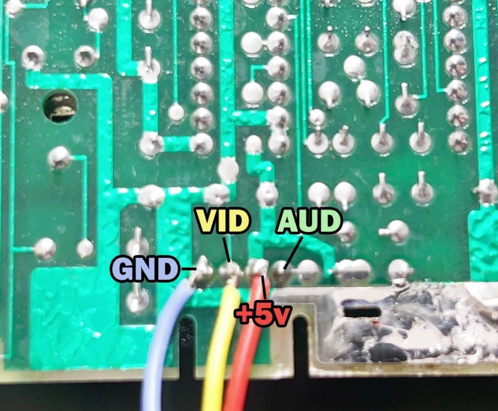
The signals that we find on the connector that connects the RF modulator are these:
(starting from left to right, seeing the board from the soldering side)
- GND
- Video
- + 5V
- Audio
With this modification the signal is perfect and nice crisp (for what can be a composite).
Joystick fix
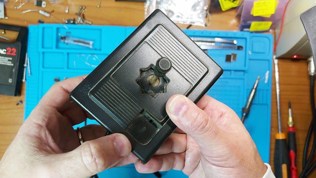
Now all that remains is to repair the joysticks !, on both the fire button is missing and opening them I found that one has a very damaged membrane and in fact does not make any contact when pressing it, the other has a perfect membrane but the stick lever is very, very , very rusty. On both there are signs of water, only on one it remained right inside and ruined the membrane, while the other is superficially.
Now, after having disassembled them, cleaned them and left the rods soaked in vinegar for 24H, I removed the rust and I also started to check the cable that it was not interrupted. Everything ok, the cable is perfect, the membrane of one joystick was already ok so I tested it and the result was excellent, the other I had to rebuild the tracks with a conductive pen, but in the end this too recovered.
Well, but the button? already everything working but the fire button of the joysticks is not there, here we need the good MacGyver

In these cases the solutions can be multiple. One that came to my mind is to use a microswitch, but since the pad worked well I preferred to leave everything as original as possible by creating the missing key with the 3D printer.
Originally the key was designed with a long rod that pressed on the membrane and a spring between the key and the joystick that held it up, while a metal stop was used to prevent the key from coming out of its seat. del joy.
I thought of simplifying it because the 3D printer does not make very resistant pieces, well especially if we are talking about PLA, so I put the spring inside and to push and not release the button I created a ring around the rod with the base larger in order to hold the spring. This cylinder will then be glued on the pin of the key and first adjusted to the maximum height that the key must have (when not pressed).
The whole project was created with Fusion360 and below I leave you the links for the STL file
Non perdetevi il video della riparazione così da avere una visione completa 🙂
If you want to support the channel, subscribe, leave a like if the video is to your liking. Write a comment if you have any doubts, questions, thanks or suggestions for other videos and enjoy!




2 Comments
Ciao ho una coppia di joystick simile a quello del video par hanno dei connettori circolari a 8 pin confermi che siano per il sistema Philips videopac?
Si, alcuni modelli hanno i joystick con cavo integrato non scollegabile, altri hanno una presa db9 e quelli che ho anche io hanno un connettore DIN.
Comunque li riconosci dalla forma e dal tasto quadrato.