In questa pagina vedremo come funzionano le porte logiche, le funzioni base con cui eseguono le operazioni i computer e con le quali possiamo realizzare i nostri circuiti elettronici.
Sotto ogni simbolo trovate la sua tabella della verità, questa ci dice come si comporta l’uscita della porta in base ai vari segnali di ingresso.
Provate voi stessi cliccando sulle porte A – B e controllate l’uscita della porta Q per vedere come si comporta realmente.
Una volta capito il funzionamento potete realizzare un vostro schema collegandole e testandole in questa pagina.
Funzionamento delle Porte Logiche 💡
AND
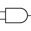
Tabella della Verità
| TO | b | Q |
|---|---|---|
| 0 | 0 | 0 |
| 0 | 1 | 0 |
| 1 | 0 | 0 |
| 1 | 1 | 1 |
OR
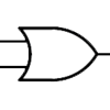
Tabella della Verità
| TO | b | Q |
|---|---|---|
| 0 | 0 | 0 |
| 0 | 1 | 1 |
| 1 | 0 | 1 |
| 1 | 1 | 1 |
NOT (Inverter)
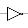
Tabella della Verità
| TO | Q |
|---|---|
| 0 | 1 |
| 1 | 0 |
NAND
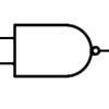
Tabella della Verità
| TO | b | Q |
|---|---|---|
| 0 | 0 | 1 |
| 0 | 1 | 1 |
| 1 | 0 | 1 |
| 1 | 1 | 0 |
NOR
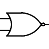
Tabella della Verità
| TO | b | Q |
|---|---|---|
| 0 | 0 | 1 |
| 0 | 1 | 0 |
| 1 | 0 | 0 |
| 1 | 1 | 0 |
XOR
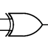
Tabella della Verità
| TO | b | Q |
|---|---|---|
| 0 | 0 | 0 |
| 0 | 1 | 1 |
| 1 | 0 | 1 |
| 1 | 1 | 0 |
XNOR
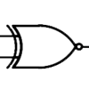
Tabella della Verità
| TO | b | Q |
|---|---|---|
| 0 | 0 | 1 |
| 0 | 1 | 0 |
| 1 | 0 | 0 |
| 1 | 1 | 1 |
Se nei circuiti integrati trovate delle porte segnate come Q̄ (notate il trattino sopra), significa che è negata, cioè l’uscita è invertita rispetto a come dovrebbe comportarsi normalmente. Negli schemi elettronici si possono trovare questi segnali per indicare che un segnale è negato o attivo basso, prendiamo l’esempio di una Eprom, il suo pin Chip Enable che serve ad abilitare la memoria (CE) se non specificato, lo standard sarebbe che si attivi se il segnale è alto, cioè 1 (5v nel caso fosse un segnale TTL). Se invece nel simbolo troviamo una bara sopra o se nella dicitura della porta troviamo scritto !CE o ~CE significa che per attivare quel segnale dobbiamo dargli un segnale invertito quindi il chip verrà abilitato se forniremo un segnale basso, gnd (0v).
Se osserviamo il simbolo delle varie porte logiche possiamo vedere che su alcune c’è un cerchietto in uscita, questo indica che l’uscita funziona in modo inverso, come prima è negata e quindi se in base al simbolo l’uscita dovrebbe essere 0, verrà portata a 1 e viceversa esattamente come se dopo l’uscita fosse collegata una porta NOT.
Tutte queste porte logiche possono essere messe a cascata e formare un circuito in grado di contare o memorizzare dati (con l’aiuto di un flip-flop).

