
Joystick C64 vs Joypad NES
16 March 2021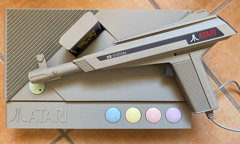
Atari XEGS repair
28 March 2021Even the Aquarius only has an RF video output, a big limitation today, given that the analog RF signal went out of use years ago and it is increasingly difficult to find a device capable of handling it.
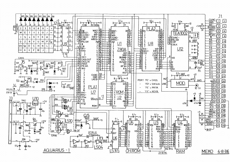
On this model there is very little on the net given its poor success and few sales, I did some tests thanks to the scheme which fortunately is found without major problems !. I have tested 2 different types of modifications and I am posting their results.
Step 1: Let's open the computer
To open the case of this computer, just remove the 6 visible screws (not those under the rubber pads and under the adhesive that are used to hold the shield.)
To open it, the cartridge must first be removed (if inserted) and a little attention must be paid to the keyboard flat, remove it by taking it near the connector.
Step 2: We disconnect the modulator
Here too we have to remove this iron block !!, nothing difficult, use a soldering iron with a large tip and that warm enough to prevent the heat from dissipating on the ground tracks since they are connected entirely on the pads. Once the area is well heated, remove the tin with a blower or with a desoldering braid and straighten the tab of the modulator to allow it to be extracted. Once all the pins of the modulator have been unsoldered, try to remove it and if any tab is stuck with tin, use the soldering iron to heat it up and facilitate removal.
Step 3: We connect the composite output
This is the most interesting part !! the TEA 1002 is the chip that generates the composite signal that is sent to the modulator which we obviously removed.


The signal must be amplified to be able to see it on a monitor / TV so I used the simple circuit used on Atari2600 and then I put the diagram back to you
1st TEST not working

The GND signal can be easily found on a point of the modulator for the screen.
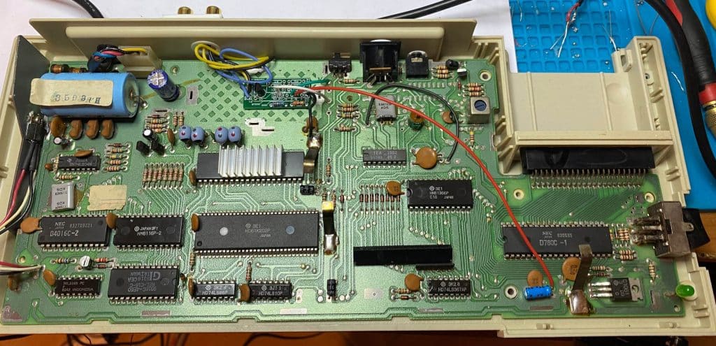
2nd TEST VIDEO OK
Why did I leave you the non-working trial? well, because the connection pins are those! and also because if it occurs to you to do the same, you already know it won't work.
So to get a good video signal out, you need to use an amplifier that will do an excellent job with a few other passive components.
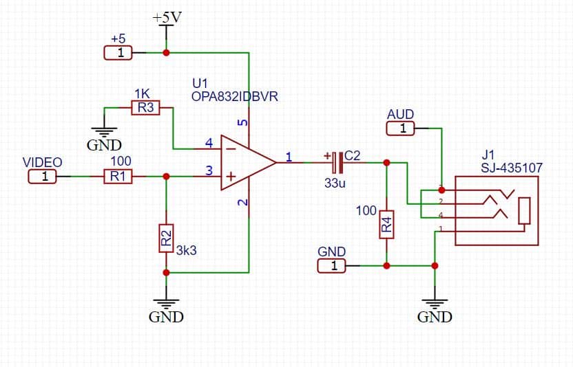
This is the scheme I used to amplify the signal and get a good video output, it is not perfect but starting from a non-optimal signal it is difficult to do better, the alternative would be to output it in RGB.
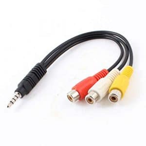
This is the working schematic, I used an OPA832 and some capacitor / resistor. I took the Audio and Video signal to a 4-pin jack so I could use a jack-to-AV cable or adapter like this one.
Step 4: Finish

A / V output with RCA and 3d print
Now all that remains is to bring out the RCA connectors for the audio and video connection.
Removing the modulator you have a hole to pass a cable but or possibly put a connector, but if you also want to put an audio connector without piercing the case you need to adapt with a 3D printer or use a 4-pin jack to be able to then use a ready-made audio / video cable.
Now close everything and enjoy the composite signal !.
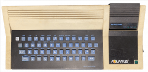
Aquarius
Aquarius the computer of the 80s from Mattel. Discover its features and how to adapt it to TV



2 Comments
Great advice, I performed the OP832 composite mod yesterday, works like a charm!
It’s one of the few modifications that looks really good and clean. 🙂