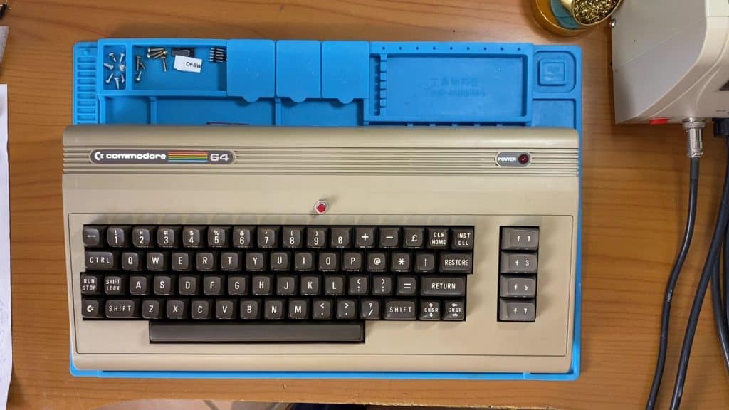
I took this C64 with black screen defect to try to see what problem may be behind it. This is a fairly common defect for the C64 and the causes can be many, and sometimes even more than one !. Well, let's not be discouraged and patiently begin to check the computer step by step.
Where to start ?!
The first thing to check as already explained in this article it always starts with possible and simple failures! It may not seem possible but I saved a C128 because it had a bad ignition switch and a C16 that had a bad 7805 regulator.
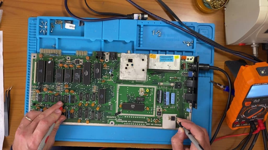
So even if it seems obvious, we check the presence of the 5V on the regulator, on some integrated and on the ignition switch, we also check the 9v ~ to make sure that everything on this side is ok. Now we can proceed with a simple "deadtest" cartridge test, this test is to rule out a problem on the ram and on the roms .. not that it cannot have more than one, but if the computer starts we can already locate the problem. Faulty CIAs and PLAs will not start the deadtest screen, the CIAs can be removed if they are bogged down .. the PLA unfortunately serves whole!
If we use the Deadtest we can remove the CIA, the ROMs and the SID and we will be able to see the test screen. In this case it didn't help me, I checked the PLA and SID on another card and verified that the only fault was the SID (sound chip) but it did not prevent the computer from booting.
So the fault was still there !.
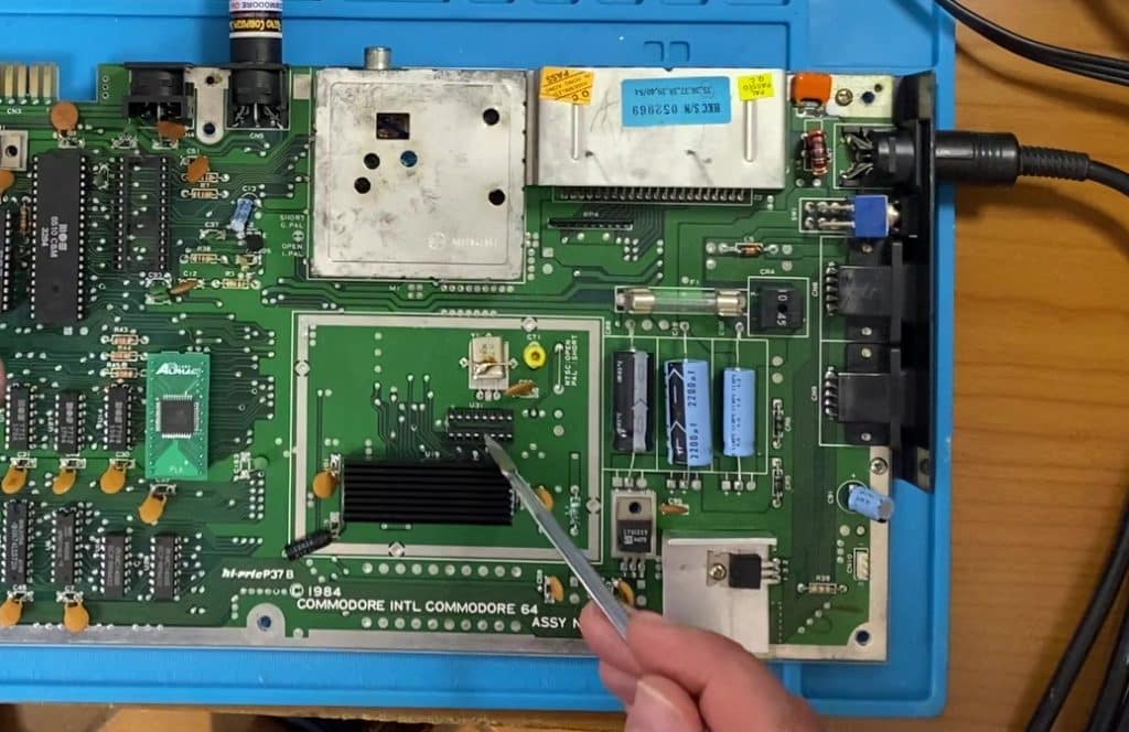
If you have an oscilloscope or a probe for logic signals it is possible to check if there is data passing on the ram, on the cpu and maybe even see the clock! This can make us limit the problem to the CPU to the ram or control logic. Also check the reset line which must be low at power up and go high after about 1 second, if it remains low there is a problem on the 555 or in the reset circuit. I noticed on this 64 there were no signals on the data bus. I tested the VIC (video chip) on another card (attention that it must always be a MOS65xx and not the new model that uses the MOS85xxx) and it was working.
With the oscilloscope I checked the clock on pin 1 of the processor, the 6510 and there was no signal, so either the clock did not work or some trace could be interrupted, but instead the signal was not on the chip that generates the clock (MOS8701)
It does not end here...
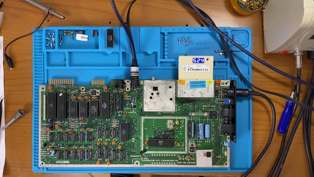
Once the clock was fixed I was able to test the computer with the Deadtest, without I had an “out of memory” screen which indicates a problem on the ram. In fact, with the video flashes made from the cartridge I identified 2 defective memory banks and the piggyback method was not even needed to test them. Usually putting the good ram on top of the bad one could start the computer, but only if the bad one is not shorted and if it does not communicate on some cell or not at all. But in other cases it could still give an error in the verification and this is the case. I unsoldered the first and then through the flashes I also found the second .. and luckily we stopped here !.
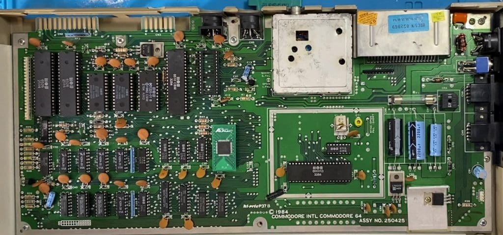
Here you can see the 2 ram replace, the missing SID and the 8701 recovered from an old faulty board, the PLA was good but I used it on the other board and here I put a compatible one as the SID will also be one of the new generation.
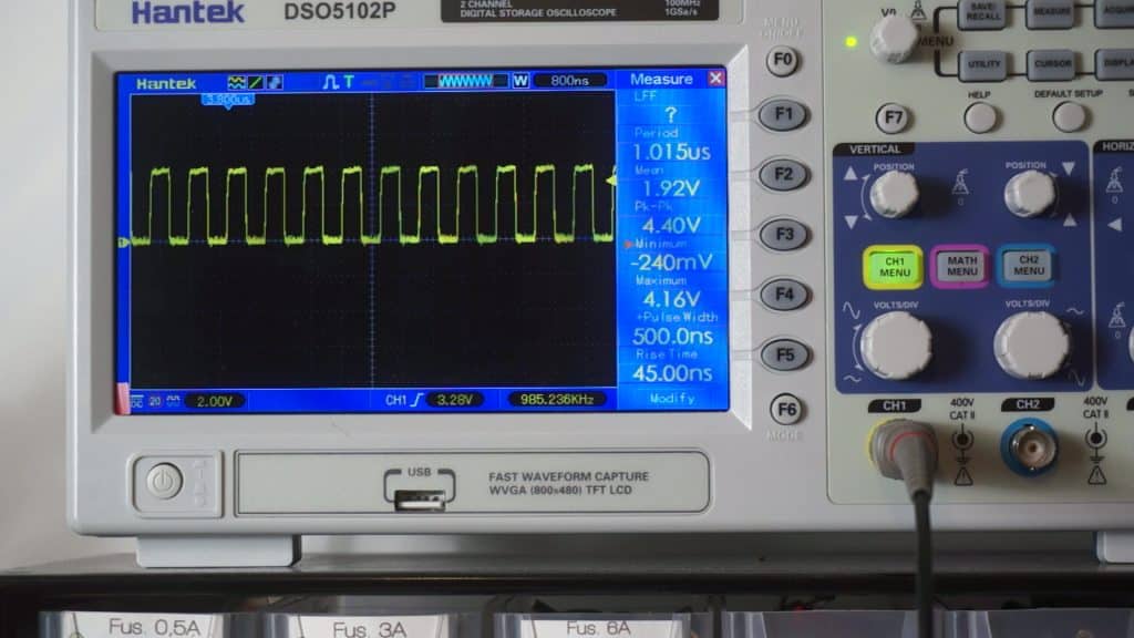
Beside the clock signal on pin1 of the 6510 with the MOS8701 working.
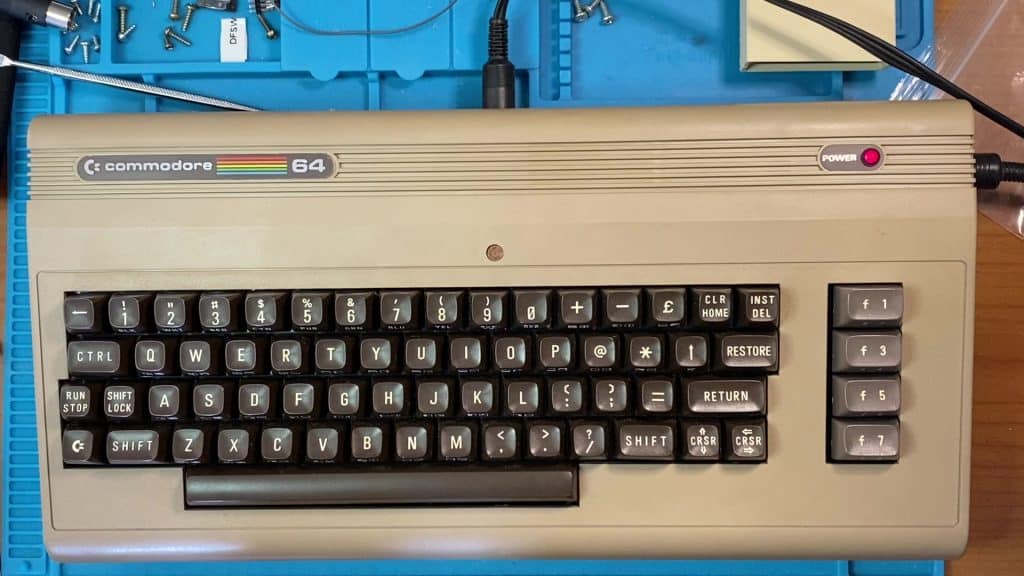
I removed the old reset button because I don't like these ugly changes on the case, unfortunately the hole remains and the solution is to cover it or try to camouflage it ..
I tried to camouflage it with a brown 3D printed button that doesn't protrude more than 1mm. The result is not beautiful but better than that protruding grope!
If you are interested in inserting the reset button on the C64 (perhaps not on the case so visible!) The pins to be used can be found on the user port of the C64 (the one on the left as you see it from the photo, under the writing C = Commodore), the pins to use are n.1 (gnd) and 3 (reset), pin 1 is the first at the top starting from the right (the one closest to the cassette holder).
Don't throw these cars away
If you have one of these machines in the attic, in the cellar, in the closet, perhaps not working and not even in good condition, do not throw them away, in the worst case if they are not recoverable they can be reused to save others, but in most cases they can revive. !. So instead of throwing them away, maybe think about donating them, if you want to make a donation, use the page contacts for information.
We use cookies strictly necessary to ensure an optimal experience in browsing the site. By clicking on "Accept all", you allow us to use all cookies. You can always review your consent by clicking on Cookie settings. We use cookies on our website to give you the most relevant experience by remembering your preferences and repeat visits. By clicking “Accept All”, you consent to the use of ALL the cookies. However, you may visit "Cookie Settings" to provide a controlled consent.
This website uses cookies to improve your experience while you navigate through the website. Out of these, the cookies that are categorized as necessary are stored on your browser as they are essential for the working of basic functionalities of the website. We also use third-party cookies that help us analyze and understand how you use this website. These cookies will be stored in your browser only with your consent. You also have the option to opt-out of these cookies. But opting out of some of these cookies may affect your browsing experience.
Necessary cookies are absolutely essential for the website to function properly. These cookies ensure basic functionalities and security features of the website, anonymously.
Cookie
Durata
Descrizione
cookielawinfo-checkbox-analytics
11 months
This cookie is set by GDPR Cookie Consent plugin. The cookie is used to store the user consent for the cookies in the category "Analytics".
cookielawinfo-checkbox-functional
11 months
The cookie is set by GDPR cookie consent to record the user consent for the cookies in the category "Functional".
cookielawinfo-checkbox-necessary
11 months
This cookie is set by GDPR Cookie Consent plugin. The cookies is used to store the user consent for the cookies in the category "Necessary".
cookielawinfo-checkbox-others
11 months
This cookie is set by GDPR Cookie Consent plugin. The cookie is used to store the user consent for the cookies in the category "Other.
cookielawinfo-checkbox-performance
11 months
This cookie is set by GDPR Cookie Consent plugin. The cookie is used to store the user consent for the cookies in the category "Performance".
viewed_cookie_policy
11 months
The cookie is set by the GDPR Cookie Consent plugin and is used to store whether or not user has consented to the use of cookies. It does not store any personal data.
Functional cookies help to perform certain functionalities like sharing the content of the website on social media platforms, collect feedbacks, and other third-party features.
Performance cookies are used to understand and analyze the key performance indexes of the website which helps in delivering a better user experience for the visitors.
Analytical cookies are used to understand how visitors interact with the website. These cookies help provide information on metrics the number of visitors, bounce rate, traffic source, etc.
Advertisement cookies are used to provide visitors with relevant ads and marketing campaigns. These cookies track visitors across websites and collect information to provide customized ads.

