Silcom pong in composite
13 August 2022
Micro Arcade Gamez mod
7 September 2022A whole pong Discrete
Here is the story of this all Italian Pong and all with discreet components!
Already here we do not find any custom chips, no microcontroller or processor, only transistors, resistors, capacitors, some coils and 3 logic gates.
With only these components, there are not a few !, we can make a ball that bounces on the screen controlled by 1 or 2 paddles and we can also generate a sound effect on the bounce.
Produced by Zanussi towards the end of 1974, this console is very reminiscent of the Magnavox Odyssey for its construction, even if the Odyssey is more complex and has implemented a cartridge slot that in reality closes only contacts, changing the style of the game a little. .
Let's go back to pong, I got this one on a well-known online auction market! and it was sold as working, too bad it wasn't quite like that when it arrived.
It certainly took a few hits during transport and since on the pcb we also find the power transformer, heavy and soldered on the board, it is likely that this has broken the printed circuit with its traces.
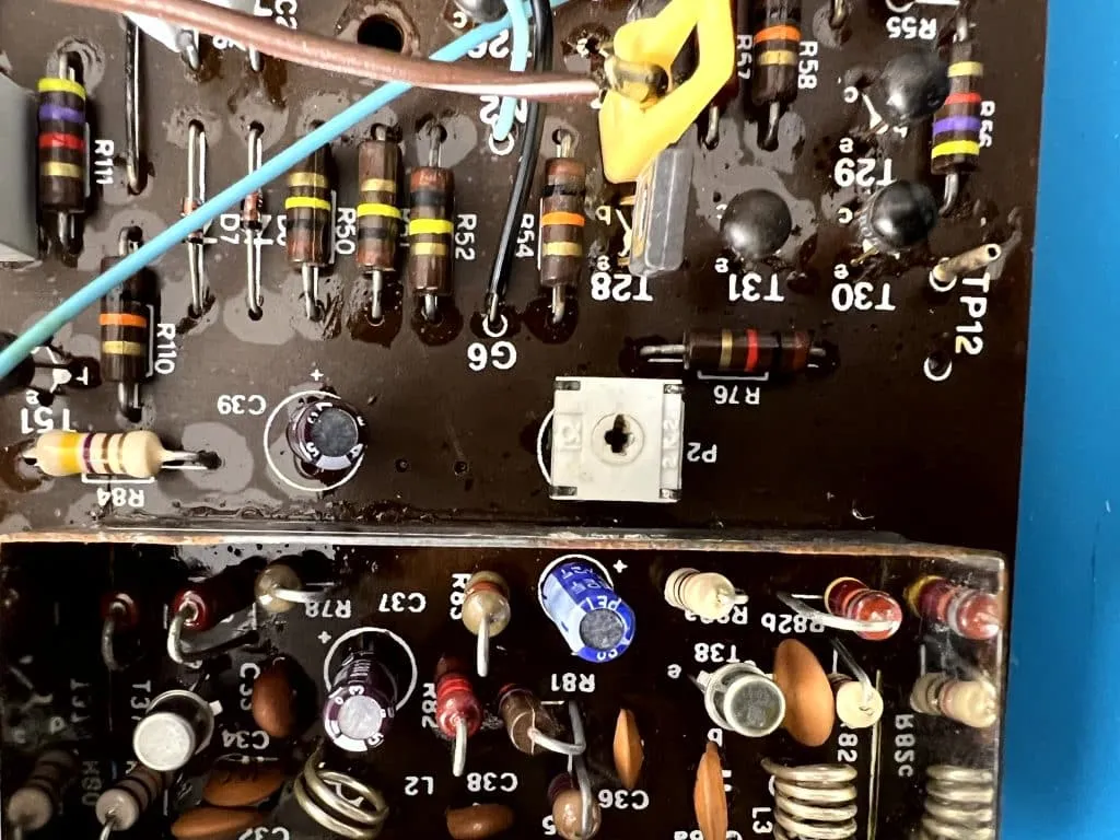
This was the state of the circuit board when it got home !.
Well, nothing complicated, I had to scrape the tracks to be able to put a lot of tin on it and redo the track.
After this work the console turned on again but it was not fully functional, one of the two pads did not generate the classic racket that could be expected, but a set of lines and noise.
This defect was certainly not the fault of the transport, but it is a malfunction of the console.
Unfortunately for this console I have not found a scheme to be able to follow the circuit in a simple way and solve the problem.
Let's go composite ...
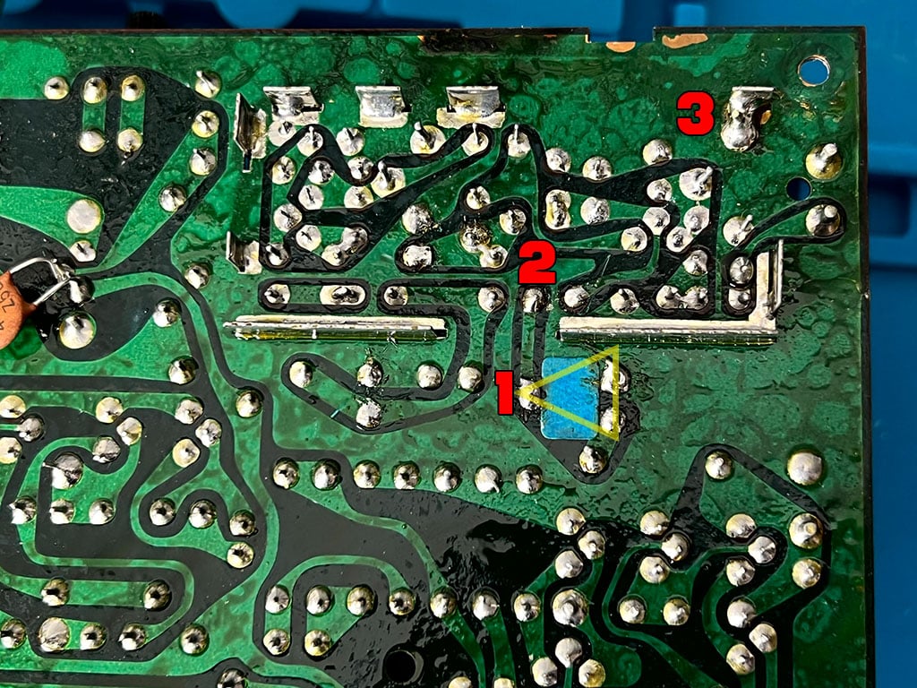
This is the lower part of the pcb, I marked in yellow the trimmer and points 1 (composite signal) and 3 (GND) useful for composite editing.
Pin 2 is a capacitor that carries the composite signal to the modulator, but since this emits a lot of noise, if we want a cleaner sengale it will be necessary to unsolder pin 2 and raise the capacitor pin to stop the modulator's disturbances from passing.
And here is the whole circuit where I got the signals.
On the integrated 7400 I took the + 5V, but the positive is very disturbed and I had to filter it with a diode and a capacitor.
The GND is found almost everywhere while the yellow wire is the video signal.
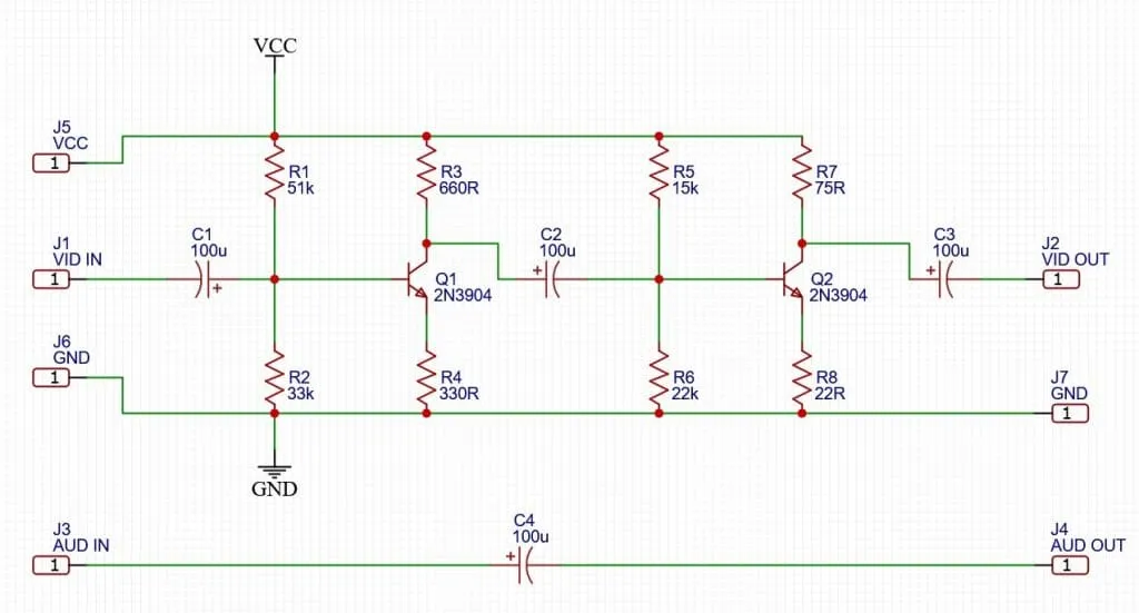
To amplify this signal I used the same modification for the Intellivision and here on the side we find the scheme, obviously here we do not need the audio part that will be managed directly from the console.
If you want to know more about this mod check the article of theIntellivision.

