
Atari 2600 7800 composite mod
19 October 2020
Atmel ICE not recognized
20 November 2020The restoration

I recovered a working CPC464 but with out of order cassette player and it had an external cable to connect an mp3 player, also badly connected to the recorder.
The first thing is to clean the computer and after taking it all apart, I found the keyboard in very bad conditions of dirt and rust… well, all keys are off!
Below you will find the details of the steps, the rust was removed with a bath in white wine vinegar and the deeper rust was scratched.
I printed some caps to cover the key holders since they are not removable (you can also do with paper tape) and then painted first with an antirust primer and finally a black paint .. I had finished the opaque one but the result is excellent and however it is not seen when everything is closed.
After a good cleaning of the keys and plastics I dedicated myself to the recorder which unfortunately has a couple of gears so worn that it cannot spin the tape, well not bad since I would have used it with Arduino. I then disassembled the recorder to be able to reinsert it in the future if I wanted to restore it to its original shape and now off with the MOOOOD!
TZXDuino
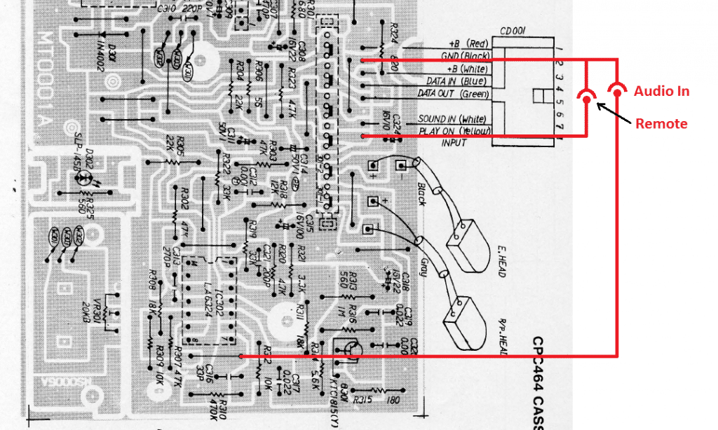
First you need to locate the points where to connect the Arduino audio signal to load the programs, follow the diagram, the remote signal is not necessary.
TZXDuino you can find it already done on various internet and auction sites or if you want to try your hand at its construction, here you can find the diagram I used for my version.
Attention!
The menu key is on pin D8 while on the firmware that is on the network it is on D7, you can change the diagram or remap the pin in the Arduino code.

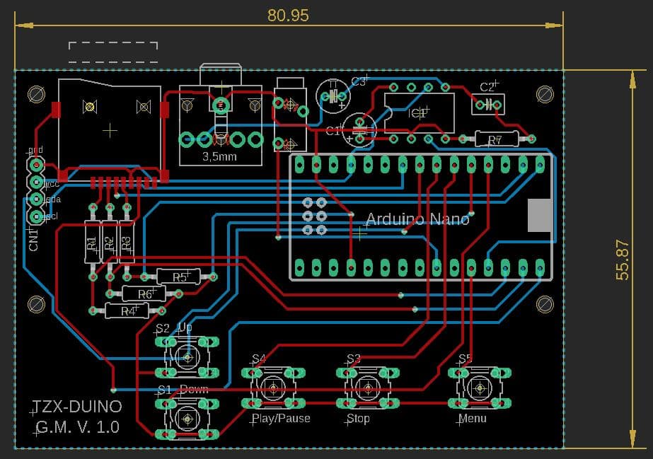
I am attaching the project that I used and created with Eagle.
The firmware used at the time of the article is 1.14
you can download it here:
http://arduitape.blogspot.com/2019/05/tzxduino-114.html
or directly from this site.
To integrate everything into your computer, you need a 3D printer and some time to dedicate to it, but the result is really beautiful.
Since I didn't want external cables to the computer or even pierce the case to put a jack for the external reader and also because I had a nice useless reader on board the car ...
here is the idea of integrating everything into the computer so as to avoid even having to power the Arduino externally!
When loading some games I encountered a reading error, I am attaching the possible errors that the CPC464 can give:
- Read error a: The signal is dropped or timing is incorrect.
- Read error b: CRC error.
- Read error c: Invalid file type / seems to be used with “CAS CHECK”. This is where you are comparing data in memory with data written to tape. So effectively a verify that data was written correctly.
- Read error d: Block is too large to fit in the buffer. (given when you do a CAT on large blocks)
All-in-one
I got carried away and since I can also use the 3D printer I created a cover for the cassette slot and one for the keys of the recorder where I placed the microSD card reader.
Here is the prototype for a 2 × 16 display I had at home, be careful because not all displays are the same size.
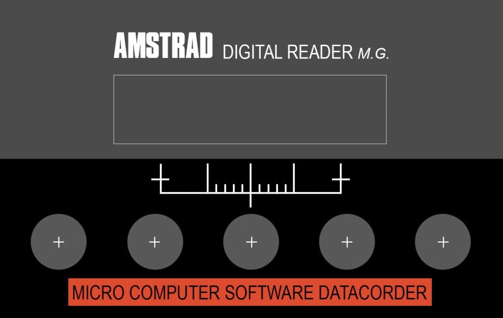
For the keys I used 12 × 12 with colored caps, I welded them on a support of a base with a thousand holes screwed to the cover, finally I printed a sticker to make the cover a little nicer.
Although it is likely that the dimensions of the display are not identical, I am attaching the file I made for the covers that do not have hooks to hold but must be glued with hot glue on the computer. If you prefer you can add the supports to avoid sticking them, I made them in a hurry and I put in the bare minimum.
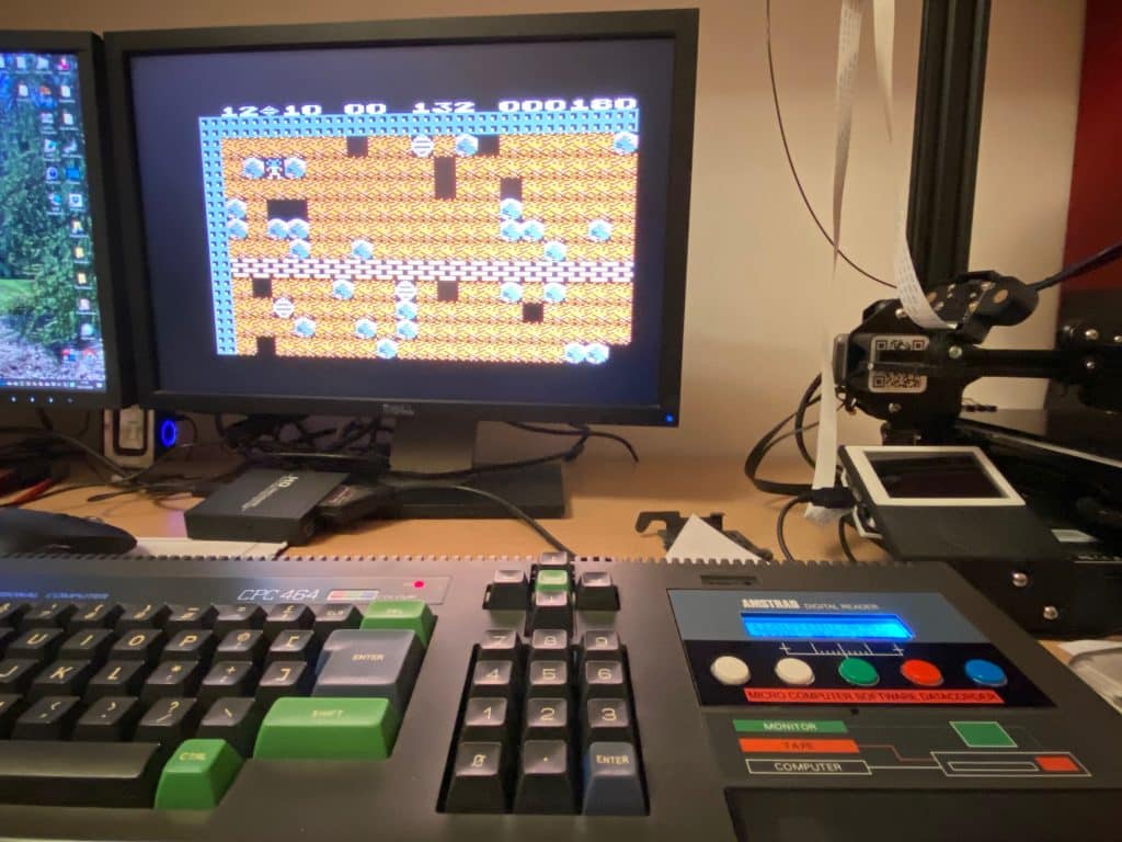
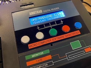
Job done! after two days of cleaning, measurements, prints and welding, here is the result.



9 Comments
Hey Mirco
The link to the CPC464 schematics is broken. It is:
https://retrofixes.it/wp-content/uploads/2020/11/464_Audio_CD_Port.png
but it should be:
https://retrofixer.it/wp-content/uploads/2020/11/464_Audio_CD_Port-1024×614.png
Best regards
Futian
Thanks for the report, I have updated all the links and images.
After an update all images were working but had lost the link to the source.
Hi Mirco,
What a great project – I stumbled upon this when looking for something exactly like this for a CPC464 I have without a tape deck. I was going to follow the instructions but noticed that the buttons on the Eagle PCB are arranged differently than the STL file for the 3D printed cover? The UP/DOWN buttons specifically. Also, it the sticker that you created available for download?
Sorry for all of the questions – I just think it’s a really neat project and would love to give my CPC464 the same treatment!
Thanks,
Mark.
Hi Mark,
the layout of the keys is different because that board is not to be put directly under the recorder, the big keys I connected on a stripboard (basetta millefori in italian) and with wires connected to Arduino.
If you look at the pictures you can see that the pcb has only Arduino and some little more components, the remaining components was connected with wires, even the microSD connector was glued under the black plastic.
I had done a very handmade job, you could make a more compact pcb and find better solutions for the components and keys.
For the graphics I will check if I find it in some folder and if so I will post it on the article.
Best regards,
Mirco.
I have updated the article and added the button to download the sticker graphic, with or without the Retrofixer logo.
Hello,
congratulations on the project.
I’m having a problem loading the software.
It gave me the following error on line 362:
no matching function for call to “Sdfat32::chdir(char*.bool)”
I’m not very experienced in programming.
Can you help me?
Thanks
I’m not entirely sure, but it seems to be an issue with the library used to read the microSD card.
You could try using a different library, or see if another version of TXZDuino works. The hardware is the standard one; maybe a button needs to be mapped to a different pin, but nothing more than that.
I didn’t write the software myself—I used what was available online at the time, and there’s probably a better version available today.
Hi,
Thanks for your reply.
I tried changing different libraries, but it keeps giving me the same error.
Could you tell me which library you use?
Thanks in advance.
Giuseppe
Hi,
this is the error I keep getting.
I can’t figure out why.
Can you help me, please?
Thanks
sd.chdir(strcat(strcat(strcat(strcat(strcat(strcat(fileName,”/”),prevSubDir[0]),”/”),prevSubDir[1]),”/”),prevSubDir[2]),true);
no matching function for call to “Sdfat32::chdir(char*.bool)”