Una CPU per il Commodore16
26 July 2024
Cartuccia C64 Aselec
5 September 2024Come non ricordare il mitico C64 con i suoi innumerevoli giochi che al tempo allietavano le nostre giornate. Se vi ricordate, per poter caricare un nuovo gioco occorreva per forza spegnere e riaccendere il computer, non c’era nessun tasto per poter ripartire senza spegnere la macchina.
In questo articolo vediamo tre soluzioni per aggiungere un tasto di reset al C64.
USER PORT
| Pin | Name | Description |
|---|---|---|
| 1 | GND | ground |
| 2 | + 5V | +5 VDC (100 mA max) |
| 3 | /RESET | Reset, will force a cold start. Also a reset output for devices. |
| 4 | CNT1 | Counter 1, from CIA #1 |
| 5 | SP1 | Serial Port 1, from CIA #1 |
| 6 | CNT2 | Counter 2, from CIA #2 |
| 7 | SP2 | Serial port 2, from CIA #2 |
| 8 | /PC2 | Handshaking line, from CIA #2 |
| 9 | AT extension | Serial attention in |
| 10 | 9VAC | 9 VAC (+ phase) (100 mA max) |
| 11 | 9VAC | 9 VAC (- phase) (100 mA max) |
| 12 | GND | ground |
| TO | GND | ground |
| b | /FLAG2 | Flags 2 |
| c | PB0 | Date 0 |
| D. | PB1 | Date 1 |
| And | PB2 | Date 2 |
| F. | PB3 | Date 3 |
| H. | PB4 | Date 4 |
| j | PB5 | Date 5 |
| k | PB6 | Date 6 |
| L | PB7 | Date 7 |
| m | PA2 | PA2 |
| No | GND | ground |


Per il collegamento esterno occorre utilizzare un connettore EDGE a 24 pin (12+12) con un passo da 3,96mm

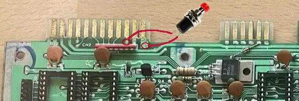
Ora non resta che collegare un pulsante tra il pin N.1 (GND) e il pin N.3 (RESET)
Come detto è possibile farlo internamente al computer ma per installare il pulsante o si buca il case o si trova un metodo innovativo magari con l’aiuto della stampante 3D.
SERIAL PORT
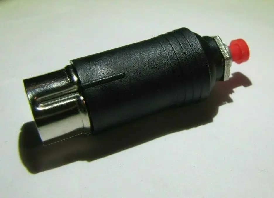
Un altro metodo per poter resettare il C64 è attraverso la porta IEC usata dal drive o stampante.
Se colleghiamo un drive 1541 o una stampante, questa avrà un secondo connettore DIN per poter collegare altre periferiche a cascata ed è possibile inserire il reset anche in queste porte.
Se si usa una periferica seriale che non ha un tasto reset o connessione passante, non possiamo utilizzare questa soluzione.
il pinout della porta seriale è il seguente.
| Pin | Description | Signal direction | Remark |
|---|---|---|---|
| 1 | SERIAL SRQ | IN | Serial Service Request In, at the C128 “Fast Serial Clock” |
| 2 | GND | – | Ground, signal ground (0V) |
| 3 | SERIAL ATN | OUT | Attention, for the selection of a device at beginning/end of a transmission |
| 4 | SERIAL CLK | IN/OUT | Clock (for data transmission) |
| 5 | SERIAL DATA | IN/OUT | Date |
| 6 | SERIAL RESET | OUT(/IN) | Reset, in older VIC-20 unused |
Possiamo trovare il segnale di reset al pin 6 (centrale) ed il GND al pin 2 (in basso a destra)



EXPANSION PORT
Eccoci arrivati all’ultima soluzione tramite la porta espansione, quella usata per le cartucce, per intenderci.
Anche su questi numerosi pin troviamo il segnale di reset e spesso le cartucce diagnostiche, le sprotettrici o fastloader hanno un tasto per il reset della macchina.
| Pin | signal | Direction (From C64) | Meaning | Remark |
|---|---|---|---|---|
| 1 | GND | PWR extension | ground | Potential is 0V on ground, signal levels are measured relative this, can also be called “common ground”. |
| 2 | +5V DC | PWR extension |
Supply voltage +5V DC |
The maximum load for extensions is 450mA. |
| 3 | ||||
| 4 | _IRQ | In/Out | InterruptRequest | see IRQ . As an output, reflects the status of the IRQ line |
| 5 | R/_W | In/Out | Read or _Write signal | High-level during read cycle, Low-level during write cycle |
| 6 | DOT Clk | Out | Dot clock frequency | 7.881984 MHz for PAL-systems ; 8.181816 MHz for NTSC-systems |
| 7 | _IO1 | Out | Input/Output area 1 indicator | Signal is low if address bus is within $DE00-$DEFF. |
| 8 | _GAME | In | Game configuration | Used for memory re-configuration |
| 9 | _EXROM | In | External ROM | Similar to _GAME. During low the internal RAM in the range of $8000-$9FFF will be switched off and _ROML will be set low, if one of these addresses occur. |
| 10 | _IO2 | Out | Input/Output area 2 indicators | Signal is low if address bus is within $DF00-$DFFF. |
| 11 | _ROML | Out | ROM Low | Low signal if the address range is $8000-$9FFF is switched off with _EXROM and one of these addresses occur on the bus. |
| 12 | B.A | Out | Bus Available | Signal from the video controller, which indicates if the bus is available during high phase of PHI2. BA=0 means VIC needs the bus during both phases of PHI2 and no other unit can use it. |
| 13 | _DMA | In | Direct Memory Access | if _DMA=Low the CPU can be requested to release the bus. It will stop after the next read cycle and all bus lines will go to high resistance state. So other units can use the computer hardware. At _DMA=High the CPU continues to work. |
| 14 | Q7 | In/Out | Data lines 7 | Bit 7 of data bus, value=128 |
| 15 | Q6 | In/Out | Data lines 6 | Bit 6 of data bus, value=64 |
| 16 | Q5 | In/Out | Data lines 5 | Bit 5 of data bus, value=32 |
| 17 | Q4 | In/Out | Datalines 4 | Bit 4 of data bus, value=16 |
| 18 | Q3 | In/Out | Data lines 3 | Bit 3 of data bus, value=8 |
| 19 | Q2 | In/Out | Data lines 2 | Bit 2 of data bus, value=4 |
| 20 | Q1 | In/Out | Data line 1 | Bit 1 of data bus, value=2 |
| 21 | D0 | In/Out | Dataline 0 | Bit 0 of data bus, value=1 |
| 22 | GND | PWR extension |
ground |
(See above) |
| TO | ||||
| b | _ROMH | Out | ROM High | Depending on the status of _GAME and _EXROM this line gets low during access to the address space between $A000-$BFFF respectively $E000-$FFFF. Condition: the internal ram area is faded out. |
| c | _RESET | In | Reset | If this line is pulled to low, all chips will be re-initialized. The program counter of the CPU will be loaded with the reset vector $FFFC and $FFFD (normally $FCE2). |
| D. | _NMI | In | Non-maskable interrupts | see NMI |
| And | PHI2 | Out | Phase 2 clock | System clock (0.98524861 MHz for PAL, 1.02272714 MHz for NTSC) |
| F. | A15 | In/Out | Address line 15 | Bit 15 of address bus value=32768 |
| H. | A14 | In/Out | Address line 14 | Bit 14 of address bus value=16384 |
| j | A13 | In/Out | Address line 13 | Bit 13 of address bus value=8192 |
| k | A12 | In/Out | Address line 12 | Bit 12 of address bus value=4096 |
| L | A11 | In/Out | Address line 11 | Bit 11 of address bus value=2048 |
| m | A10 | In/Out | Address line 10 | Bit 10 of address bus value=1024 |
| No | A9 | In/Out | Address line 9 | Bit 9 of address bus value=512 |
| P. | A8 | In/Out | Address line 8 | Bit 8 of address bus value=256 |
| R | A7 | In/Out | Address line 7 | Bit 7 of address bus value=128 |
| S. | A6 | In/Out | Address line 6 | Bit 6 of address bus value=64 |
| T | A5 | In/Out | Address line 5 | Bit 5 of address bus value=32 |
| u | A4 | In/Out | Address line 4 | Bit 4 of address bus value=16 |
| v | A3 | In/Out | Address line 3 | Bit 3 of address bus value=8 |
| w | A2 | In/Out | Address line 2 | Bit 2 of address bus value=4 |
| x | A1 | In/Out | Address line 1 | Bit 1 of address bus value=2 |
| Y | A0 | In/Out | Address line 0 | Bit 0 of address bus value=1 |
| Z | GND | PWR extension | ground | (See above) |
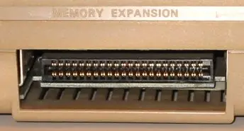


Con il connettore visto da dietro, possiamo individuare il pin C (RESET) e A (GND) come il primo e il terzo della fila in basso a destra.
Collegando un pulsante tra questi due pin otteniamo il solito reset del computer.
Purtroppo questo connettore è femmina e occorre fare un PCB per poterci connettere senza problemi, in questo caso o lo realizziamo noi alla vecchia maniera (penna o stampa fotoincisione e corrosione) oppure ne prendiamo uno già fatto o lo facciamo realizzare ai nostri fidati produttori di PCB. Volendo è possibile usare un PCB usato nelle cartucce tipo magic desk o altre simili che hanno il tasto reset, basterà saldarci solo il tasto senza componenti ed il gioco è fatto.


