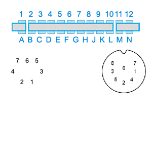
Commodore connectors
12 June 2020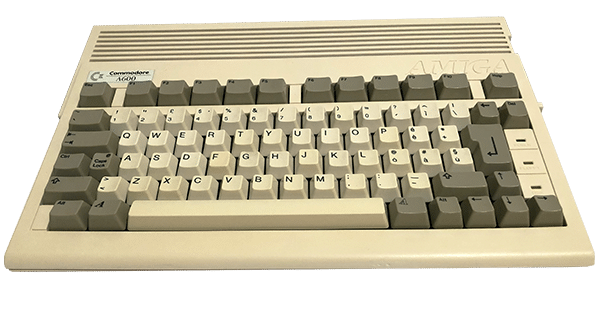


The Spectrum's RF signal is not that bad, but you can only connect it to a TV or device with an analog antenna receiver while the composite signal is easier to use on modern devices and offers higher quality.
Modifying the computer to convert it to a composite signal may seem complicated or that it is necessary to use who knows what hardware, but it is not very simple because we can find the composite signal right at the input of the modulator that converts it into radio frequency.
You will only need a screwdriver to disassemble the Spectrum, a soldering iron, a blower to vacuum the tin or desoldering iron (but if you want to cut the cables you won't need it) and a piece of cable.
I always advise you to do a job as clean as possible and not cut the cables but unsolder them in order to restore the computer to its original state in the future, but this is my thought, no one forbids you to cut the cables to do earlier and use less. instruments.
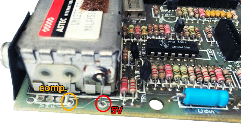
The modulator is on the left side of the board, open the cover and unsolder the 5V power cables (right cable on the photo) and the composite signal one on the left.
To unsolder them you can use a blower, or simply heat the tin with the soldering iron and extract them with tweezers. Then place them so that they do not touch anywhere, if you prefer to isolate them with electrical tape.
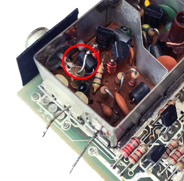
Disconnect the resistor connected to the rca connector by scanning the tin and pulling the terminal with tweezers.
Leave the resistor so that it does not touch other parts of the circuit and proceed to solder a wire (a piece of a resistor is fine too) from the rca connector to the composite pad.
Pass the cable through the third free hole of the modulator.
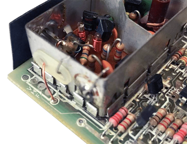
Hard?! well i'd say no, we're done.
In the photo you can see how the modification should look after the work is finished.
Now all that remains is to test if everything works correctly before closing everything.
Yes, because we probably don't have to do anything else, but in some cases it can happen that the composite signal is not clean and there is a base voltage that disturbs the signal. If so, just replace the cable with a 100uF electrolytic capacitor, making sure to put the positive pole in the composite pad of the pcb and the negative pole connect it to the arca passing through the hole used for the cable.
If everything is ok, close everything!
| Cookie | Durata | Descrizione |
|---|---|---|
| cookielawinfo-checkbox-analytics | 11 months | This cookie is set by GDPR Cookie Consent plugin. The cookie is used to store the user consent for the cookies in the category "Analytics". |
| cookielawinfo-checkbox-functional | 11 months | The cookie is set by GDPR cookie consent to record the user consent for the cookies in the category "Functional". |
| cookielawinfo-checkbox-necessary | 11 months | This cookie is set by GDPR Cookie Consent plugin. The cookies is used to store the user consent for the cookies in the category "Necessary". |
| cookielawinfo-checkbox-others | 11 months | This cookie is set by GDPR Cookie Consent plugin. The cookie is used to store the user consent for the cookies in the category "Other. |
| cookielawinfo-checkbox-performance | 11 months | This cookie is set by GDPR Cookie Consent plugin. The cookie is used to store the user consent for the cookies in the category "Performance". |
| viewed_cookie_policy | 11 months | The cookie is set by the GDPR Cookie Consent plugin and is used to store whether or not user has consented to the use of cookies. It does not store any personal data. |
