

THE GAME BOY AND HIS PROTECTIONS
18 June 2023
Mouse 1351 FIX
28 August 2023Tired of having to buy or hunt down the right ROM to replace in your VIC-20 or C64?
Now there’s the UNIRETROROM!, a universal ROM that can be used as a character, BASIC or KERNAL ROM for the Commodore 64 or VIC-20.
Configuration is dead simple: just move a jumper to switch from one mode to another, and once it’s fitted in place of the faulty ROM, job done.
It isn’t suitable for replacing the 23128 ROM used in the C64C, as that one combines both the BASIC and KERNAL functions. That memory has more pins and so isn’t compatible with this universal board.
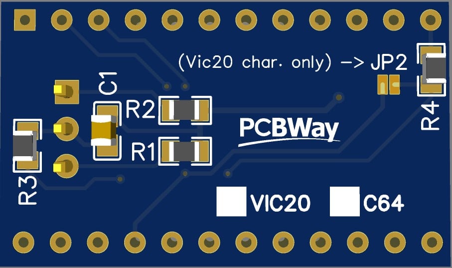
To work in character mode on the VIC-20, you need to close a jumper by soldering a blob of solder across it.
How to build the ROM
The idea for this universal memory came precisely from wanting a single component that could replace several, without having to go looking for the specific one. Handy for repairs, but also if you need to replace a faulty memory chip.
This is the schematic of the memory. It was designed to work with the 2364 and 2332 without having to configure lots of jumpers. These are the minimum that can be used.
Unfortunately, in the VIC-20 the 2332 (character ROM) uses both the CS1 and CS2 signals separately, so a small solder pad (J2) has been added in case the CS2 signal is used.
This only happens if you use it as a character ROM in the VIC-20; in the C64 it isn’t needed, because the CS2 signal isn’t used and always stays high. In the other configurations (2364) this jumper must be left open.


To build it, you can visit the GitHub page by clicking the button.
If you’d like to watch the videos on building and programming it, follow us on our YouTube channel.
How do you program the ROM?
Once the PCB is made, all that’s left is to program the EEPROM with the correct ROMs for the system we want to use.
E.g. the C64 has its own ROMs, different from the VIC-20’s, and that’s not all: you could also use versions different from those on the previous memory, such as a more up-to-date version of the KERNAL or a character ROM in another language.
You can find the various versions on this site:
C64 > http://www.zimmers.net/anonftp/pub/cbm/firmware/computers/c64/
Vic20 > http://www.zimmers.net/anonftp/pub/cbm/firmware/computers/vic20/index.html
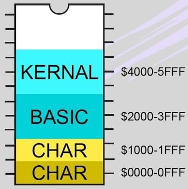
The correct sequence for building the image to write to the EEPROM is as follows:
#1 Characters (4kb) start $0000
#2 Characters (4kb) start $1000
#3 Basic (8kb) start $2000
#4 Kernal (8kb) start $4000
The character ROM has to be written twice because the memory’s A12 input might be pulled high by the motherboard.
The final image, containing all these ROMs, can be made by concatenating the individual .BIN files or with a hex editor.
Alternatively, I’ve written a dedicated piece of software to make the job easier... MAGICBIN! We’ll look at it further down.
To flash the EEPROM in the video I used the Xgecu T48 programmer, but its cheaper version, the TL866+, works just as well, as does any other programmer that can write the 28HC256.
If you use the Xgecu programmer, with Xgpro, you can create the single file directly in the memory-writing software.
Just select the memory to write first, load the first .BIN image and repeat the following loads, specifying not to overwrite the unused space and to start writing on the ROM (not from the file) at the free address after the previous data. How do I know the address? Look at the diagram above: it shows the start and end addresses of each ROM.
What's MagicBIN?
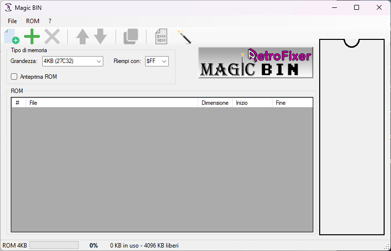
MagicBIN is a free piece of software, created specifically to simplify the process of building these multi-ROMs.
Game cartridges can often hold several game images, which are then selected via a DIP switch or in software.
To save you going mad lining up all the files one after the other, this software is the solution to our problem.
Created specifically for adding ROMs in sequence, this software lets you see how much memory is left free in the EPROM, reorder the files to easily change the sequence, check the contents of each ROM and even view a character ROM graphically. With the latest updates you can now also edit each byte by hand, or draw the character if it’s a character ROM (only 8×8 supported for now).
What do you think?
Reading the ROM with Arduino
Arduino R4 has recently come out, and its versions include the WiFi one and the Minima.
Well, what better way to make use of the matrix display built into the WiFi version than getting it to read the characters of the C64’s ROM, for example? Let’s see how to wire it up and the program you need.
If you haven’t seen the video, I recommend watching it on YouTube so you already have an idea of how these memories work, unless you know already!
A very brief description of how they work and what they do:
EPROMs, short for Erasable Programmable Read Only Memory, have a window through which you can see the chip inside, which allows it to be erased when exposed to ultraviolet light.
PROMs are different: once written they can no longer be erased. Then there are EEPROMs, which can be erased by an electrical signal applied to a dedicated pin: no more window and 15/20 minutes of ultraviolet light.
These memories (we’re talking about parallel ones) mainly have a set of input pins and other output pins (8 or 16, depending on how many bits in parallel they use), plus other pins for controlling the reading or writing of data or the chip.
E.g. during a read you simply set the address in binary on inputs A0-A12 (e.g. on a 2732; the bigger the memory, the more inputs are needed to address it), pull the chip enable and output enable signals low, and after a certain time (depending on the speed of the chip) the value at the requested location appears on the outputs.
Now let’s see how to read a small ROM with Arduino.

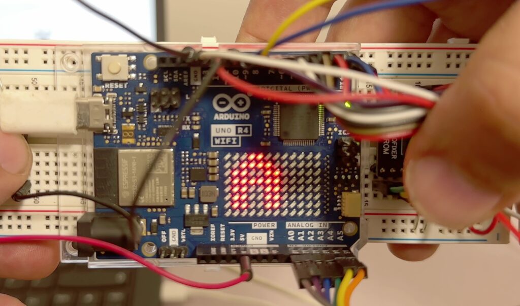
This is a small example for reading a 2732 or 2764, but not fully addressed, because an Arduino UNO or even the Nano version (the one in the schematic) doesn’t have enough pins.
To get round this you can use an Arduino Mega, or an IC that converts the signals serial/parallel.
For this test we can safely leave the EPROM’s unused inputs tied to GND. The schematic also includes a button used to advance the memory read address so that all the characters can be displayed.
This is the code used to read the ROM.
Address line A8 has been added, connected to Arduino pin D13.
					/*
* ARDUINO TEST CHARACTER ROM
* BY RETROFIXER

 * Pin Layout
 *
 *  Arduino Pin | Circuit
 * -------------+-----------
 *           A0 | EPROM IO0
 *           A1 | EPROM IO1
 *           A2 | EPROM IO2
 *           A3 | EPROM IO3
 *           A4 | EPROM IO4
 *           A5 | EPROM IO5
 *           D0 | EPROM IO6
 *           D1 | EPROM IO7
 * -------------+-----------
 *           D2 | EPROM A0
 *           D3 | EPROM A1
 *           D4 | EPROM A2
 *           D5 | EPROM A3
 *           D6 | EPROM A4
 *           D7 | EPROM A5
 *           D8 | EPROM A6
 *           D9 | EPROM A7
 * -------------+-----------
 *          D11 | CE
 *          D12 | OE
 * -------------+-----------
 *          D10 | BUTTON
 * -------------+-----------
 * EPROM A8~A12 TO GND, P (pin27) TO VCC
*/
#include "Arduino_LED_Matrix.h"

const unsigned int DELAY_US = 10;
const unsigned int EEPROM_OE = 11;
const unsigned int EEPROM_CE = 12;
const unsigned int BUTTON = 10;

int currentState;
int lastState = HIGH;
int addr=0;

// Data pins (LSB to MSB)
const unsigned int dataPins[] = {A0, A1, A2, A3, A4, A5, 0, 1};
const unsigned int addressPins[] = {2, 3, 4, 5, 6, 7, 8, 9, 13};

//Display
const uint32_t logo[] = {
		0xf01fe38,
		0xc3003003,
		0x8c1fe0f0,
	};

byte frame[8][12] = {
  { 0, 0, 0, 0, 0, 0, 0, 0, 0, 0, 0, 0 },
  { 0, 0, 0, 0, 0, 0, 0, 0, 0, 0, 0, 0 },
  { 0, 0, 0, 0, 0, 0, 0, 0, 0, 0, 0, 0 },
  { 0, 0, 0, 0, 0, 0, 0, 0, 0, 0, 0, 0 },
  { 0, 0, 0, 0, 0, 0, 0, 0, 0, 0, 0, 0 },
  { 0, 0, 0, 0, 0, 0, 0, 0, 0, 0, 0, 0 },
  { 0, 0, 0, 0, 0, 0, 0, 0, 0, 0, 0, 0 },
  { 0, 0, 0, 0, 0, 0, 0, 0, 0, 0, 0, 0 }
};

ArduinoLEDMatrix matrix;

void setup() {
  // init display
  matrix.begin();
  // Setup Control Pins
  pinMode(EEPROM_CE, OUTPUT);
  pinMode(EEPROM_OE, OUTPUT);
  pinMode(BUTTON, INPUT_PULLUP);
  pinMode(13, OUTPUT);

  // Setup Address Pins
  for (byte i=0;i<9;i++) {
    pinMode(addressPins[i],OUTPUT);
    digitalWrite(addressPins[i], LOW);
  }

  // Disable Chip
  digitalWrite(EEPROM_CE, HIGH);
  digitalWrite(EEPROM_OE, HIGH);
  matrix.loadFrame(logo);
  delay(3000);
  matrix.renderBitmap(frame, 8, 12);
}

void loop() {
  //read button
   currentState = digitalRead(BUTTON);
  if (lastState == HIGH && currentState == LOW) { // button is pressed
    lastState = LOW;
  }

  if(lastState == LOW && currentState == HIGH) { // button is released
    lastState = HIGH;
    //start
    for (int i=addr;i<addr+8;i++) {
    setAddress(i);
    delayMicroseconds(60);
    readData(i-addr);
    }
    addr+=8;
    if (addr>=512) addr=0;
    matrix.renderBitmap(frame, 8, 12);
  }
 delay(10);
}

void setAddress(unsigned int addr) {
      for (byte i=0;i<9;i++) {
        if((addr&bit(i))>0) {
          digitalWrite(addressPins[i],HIGH);
        } else {
          digitalWrite(addressPins[i],LOW);
        }
      }
  delayMicroseconds(DELAY_US);
  digitalWrite(EEPROM_CE,LOW);      // Activate Chip Enabled
  delayMicroseconds(DELAY_US);
  digitalWrite(EEPROM_OE,LOW);      // Activate Output Enabled
}

void readData(byte row) {
  int myData=0;
      for (byte i=0;i<8;i++) {
        frame[row][7-i]=0;
        if (digitalRead(dataPins[i]) == HIGH) {
            myData+=pow(2,i);
            frame[row][7-i]=1;
        }
      }
  delayMicroseconds(10);
  digitalWrite(EEPROM_CE,HIGH);      // Deactivate Chip Enabled
  digitalWrite(EEPROM_OE,HIGH);      // Deactivate Output Enabled
}

similar posts