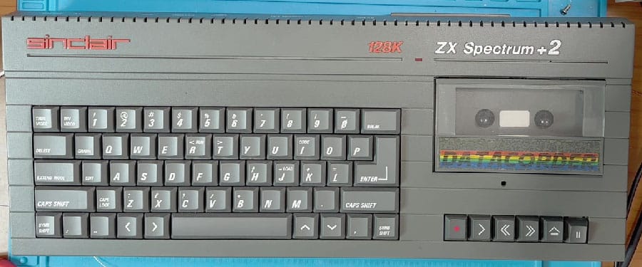
The Spectrum +2, produced by Amstrad in 1986, has a built-in tape deck for reading from and writing to tape. If its tape deck is faulty, or we simply want to load our beloved programs from SD or elsewhere, we can add an external audio input and load games from a TZXDuino or similar. Cosmetically this computer is identical to the +2A apart from the colour, grey for the +2 and black for the +2A, but what changes is on the inside!
On this computer the audio jack is mono, so it can’t be used to provide one channel as output and one as input, as is possible on the +2A. Possible solutions are to add a connector to the computer’s casing, or, for those who don’t want to spoil their original case, to opt for an external jack, or to remove the mono jack and fit a stereo connector, perhaps with the help of a 3D print if it can’t be soldered to the PCB because of its footprint.
I found 2 types of mod for adding external audio on this computer; one didn’t work!
1) Simple solution
This simple mod consists of taking our external audio signal to pin 5, the non-inverting input of the LA6324 op-amp.
I tried this mod but had no luck.
As an external player I used SVI-CAS and couldn’t load anything: the signal didn’t show up on screen and there was no way to load anything.
Maybe the signal wasn’t strong enough; perhaps with a TZXDuino things might be different…
Given how simple this mod is, I’d say give it a try, and if it doesn’t work you can remove it in a second: it’s just 2 wires to solder, audio signal and GND.
2) Solution with amplifier
If solution no. 1 didn’t work for you either, here’s this second mod, which worked for me straight away.
This mod consists of adding an op-amp, an LM358, to handle and amplify the external signal and the internal one from the tape deck. Yes, with this mod you also need to take the signal that goes from the tape deck PCB to the motherboard. Don’t worry, nothing complicated!
I removed diodes D1 and D2 and C3, which basically serve to stabilise the voltage, while D2 prevents the signal from being inverted. You can also leave them in for extra safety.
Job done! Or rather, loaded!
This is the complete mod, with the audio input taken from the 3.5mm mono jack (top right). The white wire that used to carry the tape signal to the Z80 now goes through the added op-amp, as does the signal coming in from outside. This small board outputs the new audio signal, which now goes to the Z80 (see white wire) using its connector.
Low or inverted video signal?
On this computer the video output is configured to provide an analogue signal on the output connector, but if we want to use the RGB signal we need to make this small mod. We need to check the jumper configuration; on mine LK4 was closed and LK2 open. You’ll need to fit the jumper on LK2, remove it from LK4 and check whether resistor R9 is present (it wasn’t on mine). If it isn’t fitted, you need to add a resistor slightly lower than 1Kohm to avoid the problem seen on the Spectrum +2A; one of 680 – 560 Ohm is best.
Done, now the video is perfect. Watch the video repair of this computer and of the Spectrum +2A too