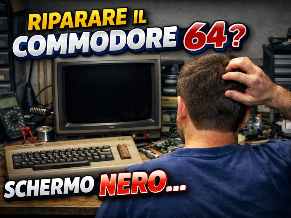
Often we are faced with a Commodore 64 with a black screen, where to start to try to fix it? This video guide is the one for you, I will try to illustrate the main points where to start checking to identify the problem. Obviously it will not be that simple, the failures can be different and sometimes more than one but if you understand the logic then the rest comes by itself !. Below I list the points that may not be clearly visible in the video, or for more detail; I may take many things for granted there, so here I try to be more precise. If anything isn’t clear, write in the comments.
Video details
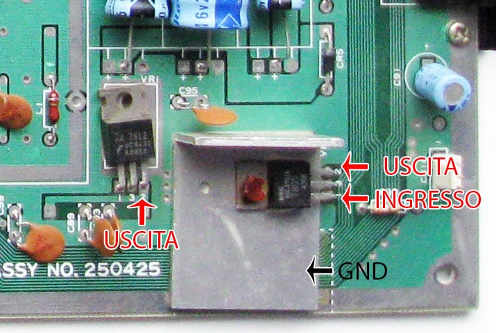
When checking the voltages, these are the regulator pins, if you check the output and you have the correct voltage it is not necessary to check the input as well, unless you want to see if the power supply does not throw out too high a voltage. The mass can be taken from any point on the cooling fin or on the mass tracks even around the breadboard. On the regulator with the heatsink (7805) we must have 5V at the output, while on the other one (7812) we must find 12V.
The first tests to do are always the same; check that when you switch the computer on:
the power switch clicks. Sometimes a faulty switch can stop the computer from powering on or from getting all its voltages. A switch that is too loose, or that doesn’t click as the contact closes when you switch it on, could be faulty or stuck. Sometimes contact cleaner spray fixes it; other times, once the spray has dried, it stops working again.
You see a flash on the video signal. The black screen must be a video signal without a picture! So as soon as you switch the computer on you should see a small flash on the screen (turn up the brightness if necessary), and on modern monitors we can tell there’s a signal because the “no signal” message disappears. If this happens, it’s very likely the problem isn’t a burnt-out VIC; watch out for poor socket contacts, though, as they can also cause a black screen.
No chips are burning hot. Leaving the computer on for a few minutes, the chips should be lukewarm; if we find a chip that’s scorching hot, it’s probably faulty.
RAM
Let's move on to the RAM, they are marked with this abbreviation, 4164, 4264 or MCM6665. Eventually if you don't recognize the name, search the internet to find out if they are 64k x1 memories. The pinout of the 4164 is this in the picture.
pin 8 (VCC) must have + 5V, while pin 16 (VSS) is connected to GND.
CIA
This instead is the pinout of the CIA, named 6526.
Pin 1 is GND and pin 20 is positive 5V.
If you also want to control the data bus with a logic probe, here we have the signals on pins D0-D7, the clock on pin 25 and the reset on pin 34 which must always be at a high level (5v), it must go low only for 1 second when turning on the computer, otherwise the problem could be the reset circuit.
SID
On the SID we find 2 voltages: ground (GND) is on pin 14, on pin 28 (VDD) we must have 12V and on pin 25 (VCC) 5V.
Also in this integrated we find the reset line (5), the clock (6) and data bus.
This is the model mounted on the C64 in the first series, then in the C64C (the thinnest white one) we find the 8580 (it is also possible to find the 6582) which unlike the previous one in pin 28 has 9V.
VIC II
In the video processor we find 12V at pin 13 (VDD), 5V at pin 40 (VCC) and GND at pin 20.
In the C64C version or the 8565 instead of the 12V we have 5V at pin 13, so they are not interchangeable with each other, but we can put an 8565 in an old version C64 if we remove the 12V from pin 13 and take the 5V in their place.
KERNAL
On the Commodore 64 with 3 ROMs (generally the first-series brown model), the Kernal is labelled 901227-0x. This is an 8Kb memory and can be replaced with a new generation Eprom like the 27C64 but the pins will need to be adapted.
The power supplies are found at pins 12 (GND) and 24 (VCC) + 5V
In the 64C models the Kernal is combined with the Basic in a single ROM MOS 8005-045 / 251913-01. This is a 16Kb memory and its pinout is this below, pin 14 (GND), pin 28 (VCC) + 5V
CHARACTERS
The character ROM is 4Kb and the pinout is this: Pin 12 GND, pin 24 VDC + 5V. Depending on the character set this ROM can have a different abbreviation, usually we find 901225-01.
To see if a ROM is working, in addition to the system of putting a finger on it and if it is on fire it is faulty !!, you can test the inputs but above all the outputs (D0-D7) to verify that the rom is doing something if enabled . To see if the memory is enabled it will also be necessary to test the CE or CS pin (chip enable or chip select) which should be active low when we select it, from the pinout we realize it because there is a sign / before the name or a line above of it and this means that the signal is inverted with respect to the standard.
If we want to verify that the ROM in addition to communicating actually has all the correct data inside or even if we have to replace it instead, this tool is for you:
XGECU
also known as minipro or TL8666II + he is an eprom reader writer but not only, he can test logic gates and also program CPLDs. A real all to do at a great price. With this programmer we can read the ROMs and verify that their content is consistent and if instead we have to replace one because it is faulty or even just to update our computer, we can take an empty eprom, download the .bin file containing the code and write it in the memory . In seconds we have a new eprom that you can use to repair your beloved computer !. I also used it to repair the Atari XEGS where I had to replace the basic ROM. The only precaution is to check the pinout of the ROM to be read that it is compatible with the new generation ones, otherwise you will have to make an adapter.
If you need to deepen the search for the fault below, you can download the C64 service manual which explains the operation and the tests to be performed to find the fault. These manuals are very useful for troubleshooting.