STADIA – Bluetooth FW Update
30 January 2023
Paddles for C64 and beyond
28 March 2023What is a RECAP ?
In electronics, recap or recapping is the name given to the procedure of replacing the capacitors on a circuit board or in a device. All the old capacitors are removed and replaced with the same number of new, better-performing ones.
Why?
Electrolytic and tantalum capacitors have a limited lifespan, a certain number of working hours, after which they start to lose their effectiveness and, in the worst cases, can even destroy themselves. The biggest enemy of these components is heat, which can quickly bring them to the end of their life sooner than expected. After many hours of operation, and if the capacitor works hard (continuous charging and discharging, high currents such as in the power section of a board), it can degrade quickly even without obvious visible signs.
What can happen?
When an electrolytic capacitor reaches an advanced state of wear, it may bulge or even burst (visible on inspection). Another less visible but more serious problem is the leaking of its electrolyte, which often causes the copper traces or the solder to corrode. This problem is less visible because the capacitor looks perfect, but in the worst cases we can spot it around the component, finding traces of oxide or a dull film in its surroundings.
Invisible damage
As well as the physical damage a capacitor can do to the board, malfunctions can arise from its loss of capacitance or an increase in its ESR (equivalent series resistance), which make the circuit work badly and can cause other components to fail. In an oscillator circuit, as in switching power supplies, where the capacitor is used to create a certain frequency to drive a transistor and the transformer, if this component fails it can easily cause the transistor to fail too, as it will end up permanently conducting.
Nearly exhausted capacitors, on the other hand, can cause interference in the audio or video section of a computer, console or amplifier.
Other invisible faults can be short circuits: yes, capacitors can short out and cause damage that way too. It’s therefore important to check that they work correctly within the circuit.
How to test them?
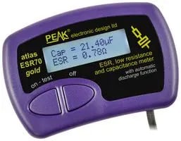
If we’re faced with a capacitor that looks fine, one way to test it is with a capacitance meter and/or an ESR meter, which will tell us whether its internal resistance is still within the expected limits.
This is one of the many instruments we can use to check the actual capacitance of the capacitor and its series resistance, which, according to a table based on its capacitance and voltage, must be below a certain value. If these parameters aren’t met, the capacitor must be replaced.
Online you can find other, even cheaper instruments for this test; search for ESR meter or capacitance meter. Both values should be checked; the instrument shown alongside measures both.
Do you need to recap?
This is a good point to clear up: some people do it regardless and others are more conservative…
It depends on what we have in front of us: which capacitors it uses, how old they are, how much it has been used and what kind of work they do. On some computers, for example, it isn’t strictly necessary, while on others it’s a must.
Let’s now look at an example, a computer that needs this procedure, as does the A600
Recapping an Amiga 1200
This computer is one of the cases where, after all these years, the capacitors can damage the traces and cause various general malfunctions. The Amiga 600 suffers from the same problem.
To do the recap you need to get the new capacitors from any electronic components shop, or you can find ready-made kits sold on auction sites.
What do you need to carry out this procedure?
These are my tools; sooner or later I’ll replace the hot air station 🙂
To desolder electrolytic capacitors, a soldering iron may be enough: heat one pad at a time while gently pulling the capacitor from the other side so the lead comes out, then repeat for the other pad until it comes out completely. With a desoldering tool, on the other hand, you can more easily go one pin at a time, but watch out for the ground traces: on the 1200 there are traces that sink a lot of heat, and it isn’t easy to suck up all the solder with a desoldering tool.
For SMD capacitors several methods can be used (it also depends on the condition of the capacitor):
1) We can heat one pin at a time with the soldering iron and pull gently, tilting the capacitor away from the side we’re heating; this will lift its pin a little, then we do the same on the opposite side, and so on until it comes off.
The capacitor mustn’t have corroded pins, otherwise we won’t manage to heat through to the pad and it won’t come off; in fact we’ll risk lifting the trace underneath.
2) Brute-force method. This consists of slowly twisting the capacitor one way and then the other (pressing lightly, not pulling!) until the capacitor’s pins break off. Twist a little at a time, increasing it slightly each time. It’s a very quick procedure but it can be risky if done badly or if the traces underneath have been damaged by the capacitor leaking.
As an alternative to twisting, you can cut the capacitor near its base and easily remove the remaining part. As with twisting, the pads then need to be cleaned of residue.
3) Hot air. By heating one side and then the other, paying attention to what’s nearby, we can remove the capacitor once the solder on its pins has melted. To make the job easier you can use flux, which will make the solder melt more evenly. This procedure is fairly safe; it takes its time, without overdoing the heat, and in some cases you need to mask the more delicate parts with Kapton tape to avoid melting nearby plastics. If the pins are corroded, you need to clean them and perhaps use flux to help the solder melt.
After removing the capacitor, you need to clean the trace with some isopropyl alcohol.
If the pad still has the capacitor’s pin on it, or is corroded, we can clean it by adding more solder and then removing it with the help of copper braid.
Once the pad is nice and clean we can solder the new capacitor on: put a little solder on one pad, then, while heating it, position the new capacitor and remove the iron.
When the solder has cooled and the capacitor is held in position, we can calmly solder the other pin; if needed we use flux, and if necessary we go over the first pin again with a little more solder.
Some useful pages about replacing capacitors on the Amiga and calculating values
Below is the repair of 2 Amiga 1200 boards and the new JBC soldering iron.
similar posts