THE SUPER NINTENDO / SUPER FAMICOM AND ITS PROTECTIONS
7 October 2023
Tapecart SD
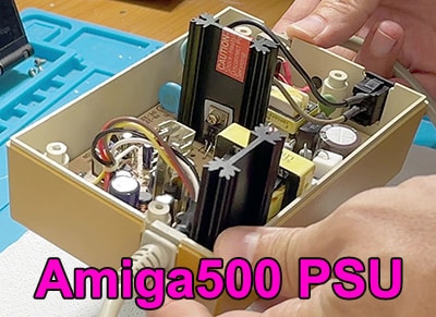
7 December 2023In this article we look at the repair of an Amiga 500 power supply that had been recapped and suddenly stopped working.
The problem was simple but well hidden, and often these things send us into a tizzy!
Analysis
As a first step, we always start with a careful visual analysis. Often the problem might be obvious or detectable by some factor, such as burn marks, oxide, black marks, odors, etc..
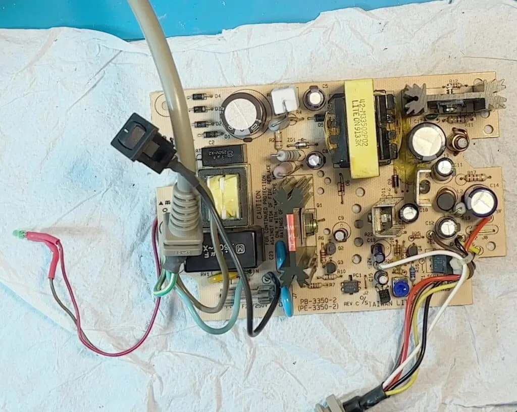
I checked the component part and visually everything was ok, soldering side I found nothing strange, no cracks or cold soldering or particular misses.
So let's start with the first tests with the circuit off and making sure that the power capacitor is discharged, in case you can discharge it with a 100~470Ohm resistor put at the ends of its leads, use a resistor of 1 or more watts, the discharge is short so we should not size it for continuous use, but neither should we put it too small to burn it out with little. I used a 270ohm of 5W.
Test
As first tests I start with the components most prone to breakdown such as diodes and mosfets/transistors. Some of these components may be affected by others and if in doubt it would be to raise a pin in the case of diodes or desolder the component in the case of a transistor.
I left out the capacitors because they had already been changed, otherwise an eye would have been on them as well.
From the first tests everything was perfect, no shorted diodes or transistors, no shorts at the input nor at the output of the power supply in short circuit, everything seems okay!
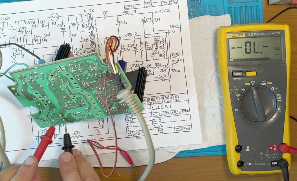
Unfortunately I could not find a schematic of this power supply, there are many versions on the net but they are all different so I am forced to go it alone, otherwise I would have followed the schematic and checked for continuity etc.
All that remains is to feed it and see what happens.
For this step we need to be very careful, we are working on a circuit under line voltage and since it is a switching power supply, the voltage is rectified and maintained by a large capacitor, here we get above 300V, which is not to be underestimated.
If we are not sure if it is working, maybe it could be shorted, we could try powering it with a bulb of about 100-150W in series, so that the current will be limited and in case of short circuit we will not blow the house switch but the lamp will light.
As soon as I powered up I checked the input voltage and it was okay, the voltage on the capacitor, okay and at the output nothing.
At this point with a diagram under hand we could go and see how far the tension went and save ourselves some work.
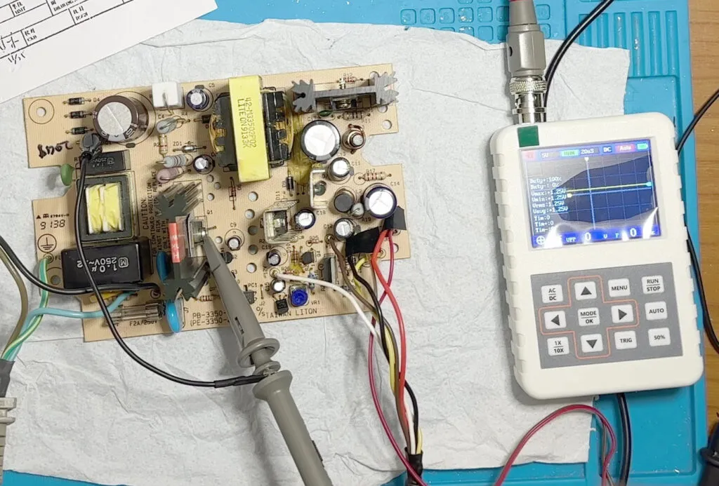
Since I did not have the schematic and did not want to get too much hands on the powered circuit, I decided to use the oscilloscope to verify that the transistors were generating the oscillation for the magnetic. Often these do not work either because they fail or because of something on the circuit such as a capacitor or something else that prevents the oscillation.
The oscilloscope I normally use is under mains and has the ground connected, it can't be used pe these measurements, we'll risk making a big bang and frying it. The oscilloscope has the ground connected to GND so if we put the gnd lead on the phase line, we have bingo! DON'T DO IT!!!
The solutions are:
remove the ground wire from the oscilloscope, use an isolation transformer or a battery-powered oscilloscope.
Well, I used a battery-powered oscilloscope, got cheap from China and really basic, but for these simple measurements it is more than fine.
From these tests I see that there is no oscillation, in fact there was not even voltage....
I test the two transistors involved and they were ok, it remained to test the phototransistor which is for feedback and could block the circuit. Testing this component is not easy, the diode side ok is good, but the transistor side I couldn't test it with a simple tester, it would be to make a small circuit and test it. Well, never mind, just change it and go, it was good!
At this point I go track by track starting from the input to the diodes and finally find the hidden fault!
A nice clean 1W resistor, no sign that it had heated, perfect as new but discontinued.
I go to replace it and the resistor colors are not as I remembered them, the last digit could have been a 3 or a 4 because it looked orange when I looked at it, but it was lighter than the other orange on the resistors I had, it looked more yellow, but again it was darker than a yellow.
I finally did some tests starting obviously with the largest resistor, so 820K... result nothing good, the power supply would go intermittently, but it would turn on!
I check the resistors around and they are all very low so an 82k fits us very well from 1W, which is too strange for an 820K.
In fact, the correct resistor was just that! Now the power supply works properly, also tested with his computer without any problem.
Watch the video to see all these vicissitudes and be sure to subscribe to the channel to support us.
Thank you

