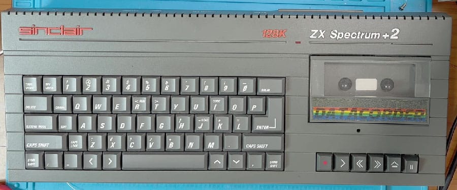
The Spectrum +2A, made by Amstrad in 1988, has a built-in tape recorder for reading and writing tapes. If its tape deck is faulty, or we simply want to load our beloved programs from SD or elsewhere, we can add an external audio input and load games from a TZXDuino or similar.
At the bottom right we can see the 3.5mm jack used for audio output when using a composite or RGB video cable instead of the RF signal. This connector is stereo, but the left and right channels are connected together, since the computer outputs a mono signal.
The most practical solution is to use one of these channels as an audio input. To do this you need to desolder the jack connector, cut the trace underneath that joins the two channels, and use the one that is no longer connected to anything as the input.
Alternatively, if we don’t want to damage our Spectrum’s PCB, we can simply bend the jack’s pin (the one on the left seen from above) and insulate it both on the PCB (with insulating tape) and on the jack with heat-shrink, so that it no longer touches the pad underneath, and with a wire we can connect it to the point where the audio goes in.
Now all that’s left is to run our input channel to the + pin of capacitor C200 on the board.
Job done! Or rather, loaded! Now close everything back up and enjoy being able to connect an external audio device to load programs.
The stereo jack will now have one channel for audio output and the other as input. To use them properly you need a splitter, but you can also build one yourself. First, take a 3.5mm male stereo jack and plug it into the Spectrum’s audio connector. With the multimeter in continuity mode, check which of the pins is connected to the audio output (the other will be the input; the GND is the long one). Now connect a female stereo jack with both channels on the pin checked earlier (the Spectrum’s audio output); GND always goes to GND, and the other free pin of the male jack should be connected to another female mono jack connector (stereo is fine too), with the signal pin on the free one of the male jack and, again, GND to GND (if you use a stereo one, always join the two L+R pins together).
Here’s an example of the splitter: (to find out which wire is the audio output, use the multimeter as described above)
Low or inverted video signal?
Here’s another thing that can happen on some motherboards: the video signal over an RGB SCART cable may be noisy or even appear in negative, with a black background and white characters.
Don’t worry, it’s not a fault; luckily it’s just down to the blanking signal being low, so the TV/monitor may not recognise it to switch into RGB mode.
To fix it, look for resistor R44, which is 1k ohm, and replace it with a 470 ohm one, or put another 1k resistor in parallel with it as in the photo.
Done, the video is now perfect. Watch the video repair of this computer and also of the Spectrum +2 (grey)
We only use strictly necessary cookies to give you the best browsing experience. By clicking "Accept all" you allow us to use all cookies. You can review your consent at any time via Cookie settings.
This website uses cookies to improve your experience while you navigate through the website. Out of these, the cookies that are categorized as necessary are stored on your browser as they are essential for the working of basic functionalities of the website. We also use third-party cookies that help us analyze and understand how you use this website. These cookies will be stored in your browser only with your consent. You also have the option to opt-out of these cookies. But opting out of some of these cookies may affect your browsing experience.
Necessary cookies are absolutely essential for the website to function properly. These cookies ensure basic functionalities and security features of the website, anonymously.
Cookie
Durata
Descrizione
cookielawinfo-checkbox-analytics
11 months
This cookie is set by GDPR Cookie Consent plugin. The cookie is used to store the user consent for the cookies in the category "Analytics".
cookielawinfo-checkbox-functional
11 months
The cookie is set by GDPR cookie consent to record the user consent for the cookies in the category "Functional".
cookielawinfo-checkbox-necessary
11 months
This cookie is set by GDPR Cookie Consent plugin. The cookies is used to store the user consent for the cookies in the category "Necessary".
cookielawinfo-checkbox-others
11 months
This cookie is set by GDPR Cookie Consent plugin. The cookie is used to store the user consent for the cookies in the category "Other.
cookielawinfo-checkbox-performance
11 months
This cookie is set by GDPR Cookie Consent plugin. The cookie is used to store the user consent for the cookies in the category "Performance".
viewed_cookie_policy
11 months
The cookie is set by the GDPR Cookie Consent plugin and is used to store whether or not user has consented to the use of cookies. It does not store any personal data.
Functional cookies help to perform certain functionalities like sharing the content of the website on social media platforms, collect feedbacks, and other third-party features.
Performance cookies are used to understand and analyze the key performance indexes of the website which helps in delivering a better user experience for the visitors.
Analytical cookies are used to understand how visitors interact with the website. These cookies help provide information on metrics the number of visitors, bounce rate, traffic source, etc.
Advertisement cookies are used to provide visitors with relevant ads and marketing campaigns. These cookies track visitors across websites and collect information to provide customized ads.